| | |
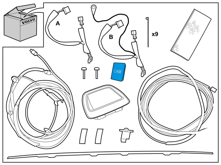
|  | | IMG-335491 |
|
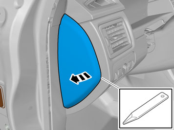
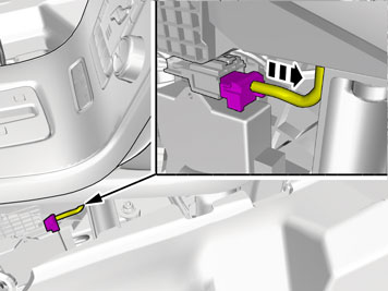
| | Preparations Place the left front seat in its rearmost position. Set the ignition key to position 0. Disconnect the battery negative lead.
Note!
Wait at least one minute before unplugging the connectors or removing other electrical equipment. |
|
|  | | IMG-254043 |
|
| | |
|  | | IMG-254044 |
|
| | |
|  | | IMG-254045 |
|
| | |
|  | | IMG-249177 |
|
| | |
|  | | IMG-226721 |
|
| | |
|  | | IMG-226722 |
|
| | |
|  | | IMG-254103 |
|
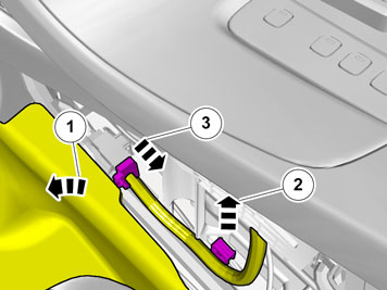
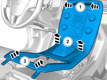
| | Remove the seat cushion (1) by pulling up its front edge, pulling it forwards and then lifting it out. Detach the two connectors for seat heating underneath the seat cushion.
|
|  | | IMG-257670 |
|
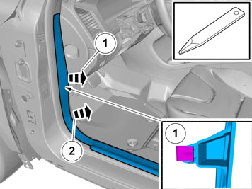
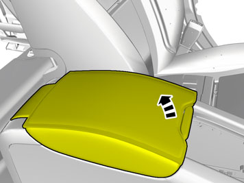
| | Fold the backrest forward. Remove the seatbelt from the guide (1) on the side bolster. Insert a hand from the side of the upper section of the side bolster. Press in the catches properly and jerk the upper edge of the bolster so that the two catches on the other side release. Lift the bolster from the mounting at the lower edge.
|
|  | | IMG-254105 |
|
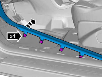
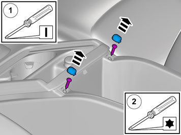
| | Remove the three clips at the upper edge of the side panel and the four plastic nuts at the lower edge. Remove the cargo compartment lighting connector. Lift out the side panel. Repeat for the other side.
|
|  | | IMG-254106 |
|
| | Measure a distance of 30 mm (1 3/16 ") from the rear edge of the rear fender and mark out a short line parallel to the rear edge. Use a piece of tape to make the markings on. Measure 30 mm (1 3/16 ") from the rear edge of the gas cylinder's bracket to the previously drawn line. Mark out the middle of the hole that is to be drilled where the lines cross each other.
|
|  | | IMG-254107 |
|
| | Use holesaw bit, part.no 9997241 (Ø28.6 mm (1 1/8")), and enlarge the hole. File down the edges of the holes. Remove any swarf. Apply primer part no. 9437350 around the hole edges and allow to dry.
|
|  | | IMG-254108 |
|
| | Measure for making holes for the rubber grommets in the trunk lid's front right-hand corner according to the diagram and mark out the middle. Pre-drill the hole using a Ø3 mm (1/8") bit.
Note!
Use a 5 mm (3/16 ") drill stop. |
Drill out the hole to Ø 8 mm (5/16 ") and then to Ø 12 mm (15/32 ") to be able to insert the pull screw through for the hole making tool.
Note!
Do not damage surrounding painted surfaces. |
Remove any swarf.
|
|  | | IMG-254109 |
|
| | Use holesaw bit part.no 9997241 (Ø28.6 mm (1 1/8")), and enlarge the hole. File down the edges of the holes. Remove any swarf. Apply primer part no. 9437350 around the hole edges and allow to dry.
|
|  | | IMG-254110 |
|
| | |
|  | | IMG-254111 |
|
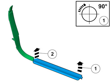
| | Remove the trunk lid's trim strip by carefully prying it off from the trunk lid and number plate lighting's panel. It is securely fastened and will eventually break. New strip included in the kit. Remove any tape residue from the trunk lid by heating the steel with a hot air gun. Do not heat above 80° C.
|
|  | | IMG-254112 |
|
| | |
|  | | IMG-346689 |
|
| | |
|  | | IMG-338119 |
|
| | |
|  | | IMG-346676 |
|
| | |
|  | | IMG-346681 |
|
| | |
|  | | IMG-346677 |
|
| | |
|  | | IMG-346682 |
|
| | |
|  | | M8502823 |
|
| | |
|  | | IMG-344717 |
|
| | |
|  | | IMG-344721 |
|
| | |
|  | | IMG-344722 |
|
| | |
|  | | IMG-341879 |
|
| | |
|  | | IMG-341941 |
|
| | |
|  | | IMG-349876 |
|
| | |
|  | | IMG-349877 |
|
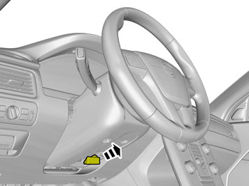
| | Remove the screws. Remove the panel.
|
|  | | IMG-348526 |
|
| | Vehicles with 5 inch ICM display Note!
If there is no connection, replace the display. |
|
|  | | IMG-352166 |
|
| | Vehicles with 7 inch display Disconnect the connector, if applicable. Use electrical tape to secure the connector in the existing cable.
|
|  | | IMG-345776 |
|
| | Note!
The number of connectors, cables and cable ties can vary in the vehicle's equipment level. |
|
| | Installing the parking camera |
|  | | IMG-255733 |
|
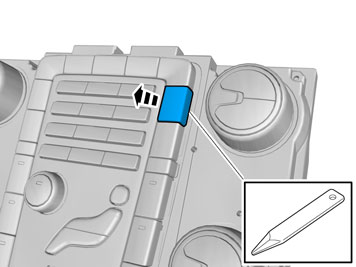
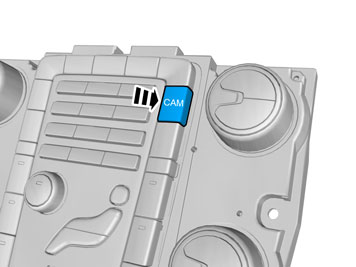
| | Installing the parking camera Drill/cut out a hole for the camera in the number plate lighting panel. Then remove the existing markings on the inside of the panel (see image). Even off the edges carefully using a fine-toothed file.
Note!
Take care not to knock the surface that the camera is to be screwed to or to scratch it so that the seal becomes impaired. |
|
|  | | IMG-255734 |
|
| | |
|  | | IMG-255735 |
|
| | Take two screws and the camera with the seal from the kit. Screw the screws into the holes on the camera completely so that they rotate freely. Insert the camera into the hole and screw it into place by tightening the screws crosswise so that the camera is tightened parallel to the panel.
|
|  | | IMG-255736 |
|
|  | | IMG-255737 |
|
| | Illustration A Take the cable harness with the two rubber grommets from the kit. The rubber grommet (1) with the shorter cable end must go through the trunk lid. Hook the cable holder onto the inner lower edge of the hinge section.
Illustration B |
|  | | IMG-255738 |
|
| | |
|  | | IMG-256323 |
|
| | |
|  | | IMG-255739 |
|
| | |
|  | | IMG-255740 |
|
| | |
|  | | IMG-255741 |
|
| | |
|  | | IMG-255742 |
|
| | |
|  | | IMG-255743 |
|
| | Take the camera equipped panel for the number plate lighting. Connect the connector to the routed cable harness for the reversing camera. Guide the cable for the number plate lighting through the hole in the trunk lid. Reinstall the panel and tighten. Ensure that the cables for the number plate lighting are not trapped.
|
|  | | IMG-255744 |
|
| | |
|  | | IMG-255745 |
|
| | |
|  | | IMG-255746 |
|
| | Note!
During installation the underlying surface must be kept at a temperature of at least +15°C (59°F). |
Insert the trim strip clips in the corresponding holes on the panel. Ensure that the strip's locating pins align with the holes on the trunk lid. Press the strip firmly along the entire length of the trunk lid and the panel so that the tape adheres.
|
|  | | IMG-255747 |
|
| | |
|  | | IMG-255748 |
|
| | |
|  | | IMG-255749 |
|
| | |
|  | | IMG-255750 |
|
| | |
| | Installing the parking assistance camera (PAC) |
|  | | IMG-255751 |
|
| | Installing the parking assistance camera (PAC) |
|  | | IMG-222282 |
|
| | |
|  | | IMG-222283 |
|
| | |
|  | | IMG-222285 |
|
| | |
|  | | IMG-255752 |
|
| | |
|  | | IMG-255754 |
|
| | |
|  | | IMG-273804 |
|
|  | | IMG-273823 |
|
|  | | IMG-273824 |
|
| | Note!
The adapter cable A was included in a previous version of the kit for the parking camera. The adapter cable B was included in a later version of the kit for the parking camera. Both versions are suitable for all cars. |
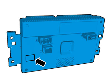
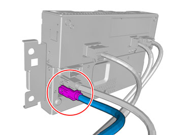
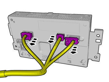
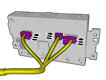
Illustration A Connect the previously routed cable harness connector (1) to the right-hand connector on the control module. Take the adapter cable A/B from the kit and connect the large green connector to the socket on the control module, as illustrated. Connect the connector (2) on the pre-routed, taped cable harness for the power supply under the left-hand tail lamp, to the corresponding connector on the adapter cable. Take the long remaining cable harness from the kit and connect the end with the gray connector (3) to the connector in the middle of the control module. Clamp the adapter cable's remaining connector using the tie strap from the kit.
Figure B shows adapter cable A Figure C shows adapter cable B |
|  | | IMG-255753 |
|
| | |
|  | | IMG-273825 |
|
| | |
|  | | IMG-255757 |
|
| | Applies to cars with a TRM module. |
|  | | IMG-255758 |
|
| | |
| | | IMG-222285 |
|
| | |
|  | | IMG-255759 |
|
| | |
|  | | IMG-273826 |
|
|  | | IMG-273863 |
|
| | Note!
The adapter cable A was included in a previous version of the kit for the parking camera. The adapter cable B was included in a later version of the kit for the parking camera. Both versions are suitable for all cars. |
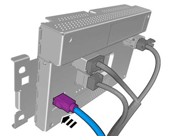
Figure A shows adapter cable A Figure B shows adapter cable B Connect the previously routed cable harness connector to the right-hand connector on the control module (1). Take the adapter cable A/B from the kit and connect the large green connector to the socket on the control module, as illustrated. Connect the connector (2) on the pre-routed cable harness for the power supply to the corresponding contact on the adapter cable. Take the long remaining cable harness from the kit and connect the end with the gray connector (3) to the connector in the middle of the control module.
|
|  | | IMG-273864 |
|
| | |
|  | | IMG-273865 |
|
| | |
|  | | IMG-255763 |
|
| | |
| | | IMG-222282 |
|
| | |
|  | | IMG-255764 |
|
| | |
| | | IMG-222285 |
|
| | |
|  | | IMG-255765 |
|
| | |
|  | | IMG-255766 |
|
| | |
|  | | IMG-255767 |
|
| | |
|  | | IMG-273866 |
|
| | |
|  | | IMG-273867 |
|
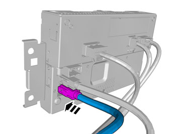
| | Connect the remaining green connector (1) on the adapter cable for the power supply to the corresponding socket in the TRM module. Connect the remaining gray connector (2), which was removed from the TRM module.
|
|  | | IMG-273869 |
|
| | Steps 70-71 only apply to cars with adapter cable B for the power supply |
|  | | IMG-273870 |
|
| | |
|  | | IMG-257676 |
|
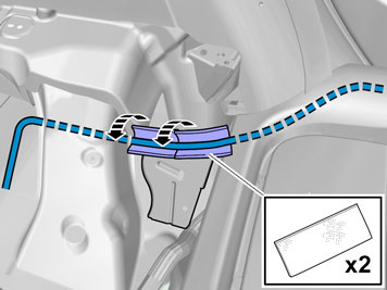
| | Route the previously connected cable harness inside the insulation panel at the left-hand rear wheel arch and out through the hole in the body. Take a tie strap from the kit and secure the cable at the fuse holder's cable harness.
|
|  | | IMG-354975 |
|
| | |
|  | | IMG-241925 |
|
| | |
|  | | IMG-353731 |
|
| | |
|  | | IMG-255771 |
|
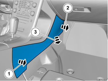
| | Pull out the B post panel at the lower edge until the two clips release. Continue to route the cable harness inside the B post panel and forwards in the car. Route the cable harness along the left-hand side, in front of the floor and insulation panels, up to the front edge of the door opening.
|
|  | | IMG-353574 |
|
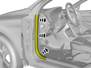
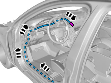
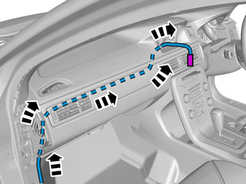
| | Only applies to left-hand drive vehicles Route the cable harness inside the floor and insulation panels, up on the A pillar slightly, and then at an angle upwards, between the A pillar and the end panel, towards the dashboard. Route the cable harness to the location for the screen in the dashboard. Place the cable harness so that it does not come into contact with sharp edges or moving parts under the dashboard.
|
|  | | IMG-353581 |
|
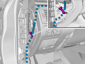
| | Only applies to right-hand drive vehicles Take a piece of wire and insert it by the air ducts through the hole for the screen. Pull it out to the left, above the glove compartment and out through the left-hand end of the dashboard. Tape the connector on the cable to the screen by the wire. Pull the cable up to the location for the screen and out through the hole in the dashboard.
|
|  | | IMG-353636 |
|
| | |
|  | | IMG-255775 |
|
| | Only applies to left-hand drive vehicles |
| | | IMG-348526 |
|
| | Applies to all vehicles with 5 inch ICM display Note!
If there is no connection, replace the display. |
|
|  | | IMG-348747 |
|
| | |
|  | | IMG-348748 |
|
| | Applies to all vehicles Note!
The number of connectors, cables and cable ties can vary depending on the vehicle's equipment level. |
|
|  | | IMG-352266 |
|
| | Applies to vehicles with 5 inch ICM display |
|  | | IMG-352267 |
|
| | Applies to vehicles with 7 inch ICM display |
|  | | IMG-349904 |
|
| | |
| | |
|  | | IMG-349804 |
|
| | |
|  | | IMG-349806 |
|
| | |
|  | | IMG-345282 |
|
| | |
|  | | IMG-339505 |
|
| | Cars with manual transmissions |
|  | | IMG-347222 |
|
| | |
|  | | IMG-345283 |
|
| | Cars with automatic transmissions |
|  | | IMG-345284 |
|
| | |
|  | | IMG-292804 |
|
| | |
|  | | IMG-340599 |
|
| | Fold back the mat. Unhook the cable harness clips. Unplug the connector.
|
|  | | IMG-341780 |
|
| | |
|  | | IMG-349811 |
|
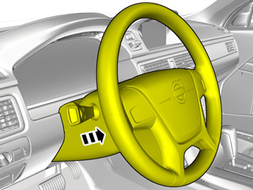
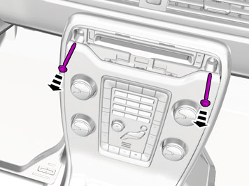
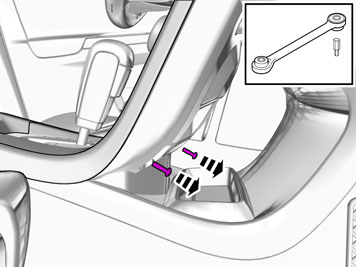
| | Remove the covers. Remove the screws.
|
|  | | IMG-292826 |
|
| | Vehicles with the 4C system |
|  | | IMG-345317 |
|
| | |
|  | | IMG-349826 |
|
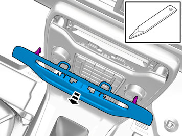
| | Applies to all vehicles Caution!
Do not damage the hooks. |
|
|  | | IMG-345295 |
|
| | |
|  | | IMG-345296 |
|
| | |
|  | | IMG-345763 |
|
| | |
|  | | IMG-353616 |
|
| | |
|  | | IMG-336901 |
|
| | |
|  | | IMG-336904 |
|
| | Caution!
When the ignition is to be switched on for the first time after the battery has been disconnected, this must be done whilst by standing outside the vehicle, stretching your arm in and avoiding the working area for the airbags. |
|
|  | | IMG-242268 |
|
| | |
|  | | IMG-354602 |
|
| | Perform a function test as follows: Engage reverse gear. The display is activated. Wait for the message "Update Environment" to appear on the screen. Follow the on-screen instructions. Switch off the ignition for at least 10 seconds. Turn the ignition on. The display is activated. Check that the support lines appear on the screen and that these react to steering wheel movements.
|