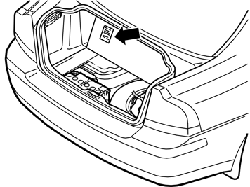
| | Cargo compartment, preparations |
|  | | A8800136 |
|
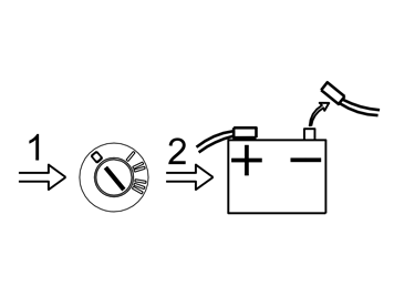
| | Cargo compartment, preparations Note!
Wait at least five minutes before disassembling the connectors or removing other electrical equipment. |
|
| | |
|  | | M8902133 |
|
| | |
|  | | M8503264 |
|
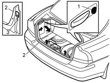
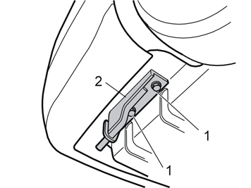
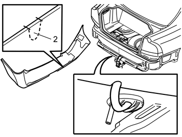
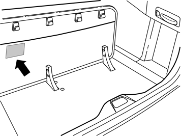
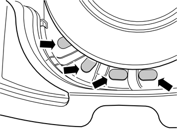
| | Turn the handle (1) on the right and left-hand sides a quarter turn. Fold the side panels inwards. Remove the panels. Pull the tailgate sill trim panel (2) forwards on the right and left-hand sides until the two clips on each side release. Carefully pull the panel with some force as it is tightly secured. Remove the wiring (3) for the cargo compartment lighting. Pull the sill trim panel straight up until the four clips on the underside release. Remove the sill trim panel.
|
|  | | M8901860 |
|
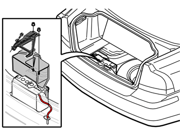
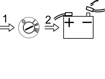
| | Remove: the two nuts from the front edge of the battery holder and the screw from the rear edge the battery holder the cover the battery negative lead the battery, or move the battery to facilitate access.
|
|  | | M8101297 |
|
|  | | IMG-213364 |
|
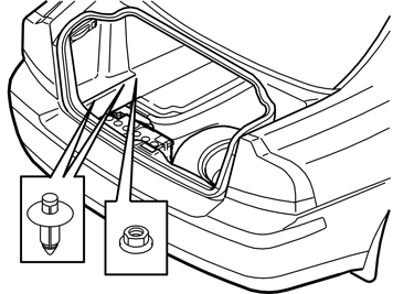
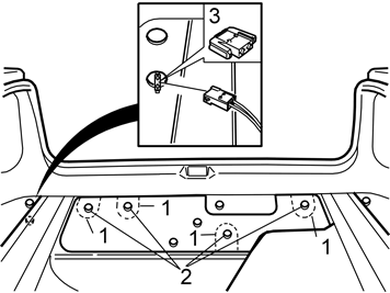
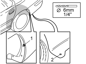
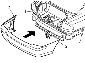
| | Illustration A Remove: the four perforated sections (1) of the insulation panel the nuts (2) for the bumper the antenna connector (3).
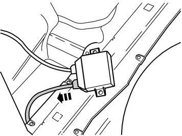
Illustration B Applies to cars with parking assistance Detach the parking assistance module (PAM) from its location on the left-hand (model year 2005–) / right-hand (model year –2004) side of the cargo compartment. Detach the smaller connector from the control module.
|
| | Preparations, rear suspension |
|  | | M8600564 |
|
|  | | M8600581 |
|
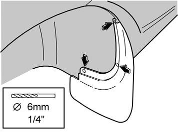
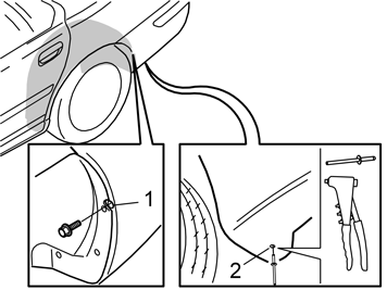
| | Preparations, rear suspension Raise the car. Remove the rear wheels.
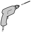
Illustration A only applies to cars with mudguards Illustration B applies to all cars Unscrew the screw (1) almost all the way on the left and right-hand sides in the rear edge of the wheel arch. Press the screw using a screwdriver until the loose end pieces on the inside of the bumper cover are pressed backwards. Carefully drill out the rivets (2) underneath the bumper on both sides. Use a Ø6 mm (1/4") diameter drill bit. Do not damage any of the plastic components.
Note!
There may be another installation procedure with more blind rivets on older cars. |
|
|  | | M8600582 |
|
|  | | IMG-213365 |
|
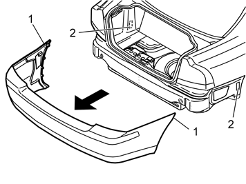
| | Illustration A Pull the bumper backwards slightly. Bend out the sides (1) so that they detach from the mountings (2). Then pull the bumper backwards until it detaches completely. Place the bumper on a clean underlying surface that will not damage the paint.
Illustration B Applies to cars with parking assistance Detach the bumper in accordance with the above. Carefully pull the cable (3) out through the hole in the car. Place the bumper on a clean underlying surface that will not damage the paint.
|
|  | | M2501103 |
|
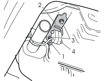
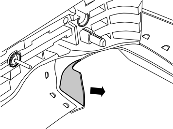
| | Remove: the rivet (1) on the bracket (2) for the silencer. Use cutting nippers the screws (3) on the bracket the bracket by detaching the rubber mountings (4). The bracket will not be used again.
|
|  | | D8600247 |
|
| | |
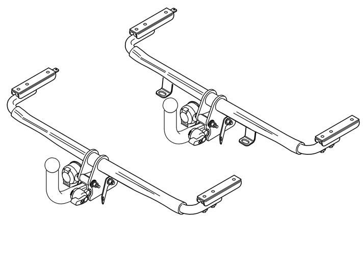
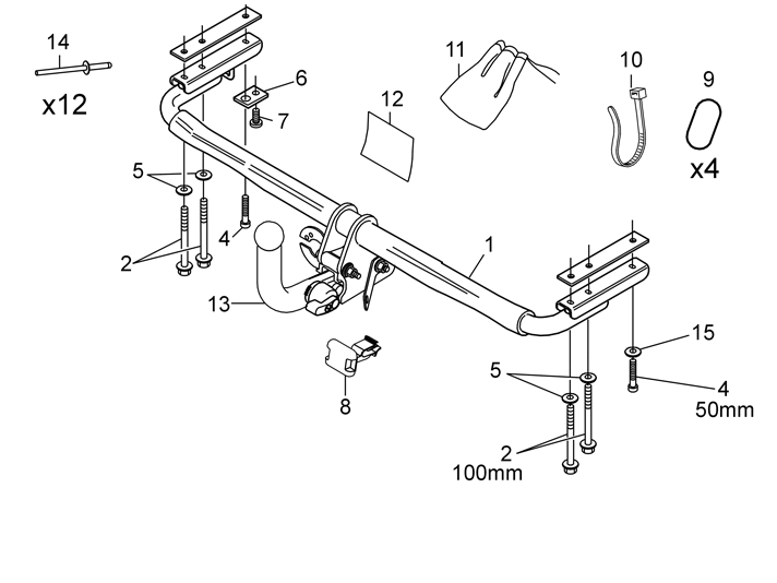
| | Installing the detachable tow hitch (including the cable harness) |
|  | | M8903848 |
|
|  | | M8903805 |
|
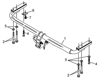
| | Installing the detachable tow hitch (including the cable harness) Illustration A Clean any underseal and dirt from the mating surfaces between the tow hitch crossmember (1) and the bodywork. Install the screws (2, 4) from the underneath with the washers (5) between. Finger tighten. Install a washer plate (6) on the left-hand side on the front screw (4). This is to secure the rear mounting for the heat deflector plate using the screw (7), (see illustration B).
Illustration B |
|  | | M8601259 |
|
|  | | M8601258 |
|
| | Note!
Particular care must be taken when cutting out in the bumper on the R-line. The brackets for the air intake's mesh could be damaged. |
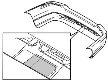
Applies to cars with chassis number (CH 425000-) EU and Australia Cut along the markings on the inside of the bumper to make the cut-out for the tow hitch. Cut out so that the marking lines remain in the bumper afterwards.
Illustration B applies to the Australian tow hitch with chain mountings Install masking tape opposite the smaller cutting lines. Cut the material out inside the marking lines.
|
|  | | M8601308 |
|
|  | | M8601309 |
|
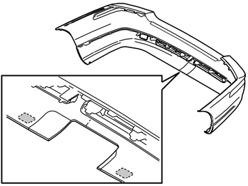
| | Illustration A applies to cars with chassis number (CH –424999) Centre the cutting template and position it against the edge, as illustrated. Carefully mark out the cutting lines around the cutting template. Cut along the markings on the inside of the bumper to make the cut-out for the tow hitch. Cut out so that the marking lines remain in the bumper afterwards.
Illustration B applies to the Australian tow hitch with chain mountings Install masking tape opposite the smaller cutting lines. Cut the material out inside the marking lines.
|
|  | | M8903417 |
|
| | Applies only to R-line Apply masking tape on the outside of the exhaust pipe clip to avoid damage from the base of the saw. Leave the masking tape in place during installation. Cut along the marked raised area and remove the cut-out area.
|
| | |
|  | | M8601204 |
|
| | Install the cable harness for the tow hitch according to the Installation Instructions for the appropriate cable harness. When installing a 7–pin or 13–pin cable harness for the tow hitch, a cut-out (2) must be made in the lower edge of the bumper. Loosely install the bumper. Make markings for the cut-out for the cable harness. Cut out as illustrated so that there is room for the cable harness.
|
| | Finishing work and function test |
|  | | M8601205 |
|
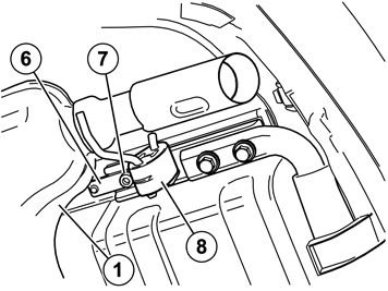
| | Finishing work and function test If the mountings (1) have released from the rear edge of the wheel arch, reinstall the mountings. Press the mountings completely back into their grooves and screw in the screw several turns. Applies to cars with parking assistance: Lift up the bumper in position. Pull the cable for the sensors through the hole for the bumper's guide, and pull the cable in from the inside. Reinstall the bumper by pressing it forwards. Ensure that the four screws protruding from the bumper align with the holes in the car. Before the bumper is completely installed, slide the top edge (2) into the grooves. Then slide the bumper fully in.
|
|  | | M8600586 |
|
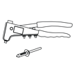
| | Tighten the screw (1) on both sides. Secure both sides of the bumper with blind rivets (2) from below. Reinstall the nuts. Tighten the nuts to 18 Nm (14 lbf. ft.).
|
|  | | M8101296 |
|
| | Install new rubber tabs over the four installed screws as follows: Align the rubber tabs (1, 4) edge to edge with the lining mat Compress the rubber tab (2) slightly to align in the cut-out Align the rubber tab (3) so that the lower edge is positioned edge to edge with the lining mat. Then cut off the section protruding from the lining mat. Do not remove too much. If necessary, cut away the area around the screw heads, so that the screws are accessible.
|
|  | | M8601207 |
|
|  | | M8503942 |
|
| | Illustration B applies to cars with integrated carrier bag holder in the cargo compartment floor Install the enclosed decal under the elastic strap on the underside of the floor hatch, as illustrated. In addition, use staples for the installation.
|
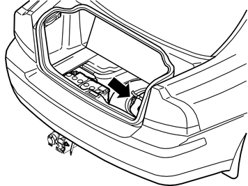
|  | | A8800137 |
|
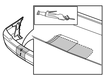
| | Reinstall: the battery, and connect the battery cables the cover the battery holder the tailgate sill trim panel, and plug in the connectors for the cargo compartment lighting the two side panels, incl. clips and plastic nuts Fold the floor hatch back into place. Remove the masking tape from the bumper.
|
|  | | M8903715 |
|
|  | | J8903481 |
|
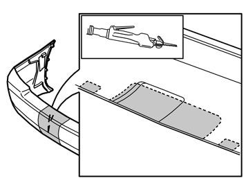
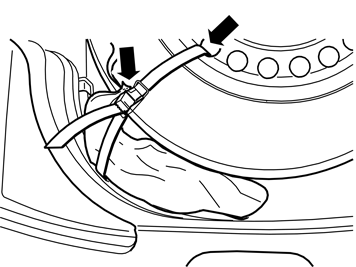
| | Storing the towbar Illustration A Remove the tow hitch and place it in the protective bag. Locate the protective bag beside the spare wheel and test location options. Clean the surfaces to which the pieces of foam tape shall adhere.
Illustration B |
|  | | J8903483 |
|
| | Place the tow hitch in the bag supplied and locate it on the previously adhered pieces of foam tape. Thread the strap in one of the holes in the wheel and strap down the bag with the towbar onto the tyre.
|