| | |
| | Read through all of the instructions before starting installation. Notifications and warning texts are for your safety and to minimise the risk of something breaking during installation. Ensure that all tools stated in the instructions are available before starting installation. Certain steps in the instructions are only presented in the form of images. Explanatory text is also given for more complicated steps. In the event of any problems with the instructions or the accessory, contact your local Volvo dealer.
|
| | |
|  | | IMG-440436 |
|
| | Note!
This colour chart displays (in colour print and electronic version) the importance of the different colours used in the images of the method steps. |
Used for focused component, the component with which you will do something. Used as extra colors when you need to show or differentiate additional parts. Used for attachments that are to be removed/installed. May be screws, clips, connectors, etc. Used when the component is not fully removed from the vehicle but only hung to the side. Used for standard tools and special tools. Used as background color for vehicle components. Used for accessory components.
|
| | |
|  | | IMG-394779 |
|
| | |
|  | | IMG-383039 |
|
| | |
|  | | IMG-383043 |
|
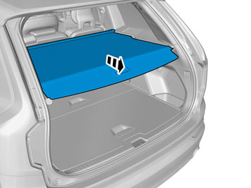
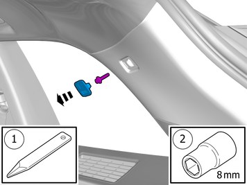
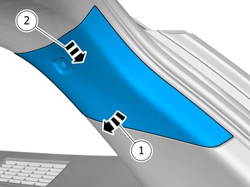
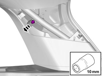
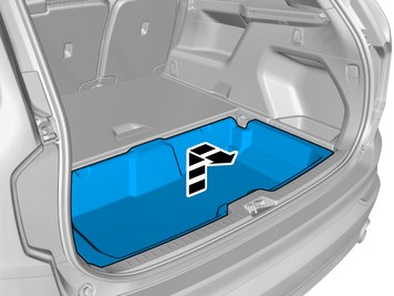
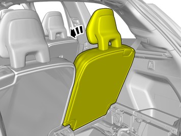
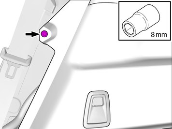
| | Remove the marked part. Remove the screw.
Tightening torque: Panel, to D-Pillar
, 4.5 Nm
|
|  | | IMG-383044 |
|
| | |
|  | | IMG-383045 |
|
| | |
|  | | IMG-383046 |
|
| | |
|  | | IMG-383040 |
|
| | |
|  | | IMG-394727 |
|
| | |
| | Vehicles with seven seats |
|  | | IMG-401374 |
|
| | |
| | Applies to all other vehicles |
|  | | IMG-383042 |
|
| | |
| | |
|  | | IMG-383047 |
|
| | Note!
Do not loosen the bolts more than 2 turns. |
|
|  | | IMG-383048 |
|
| | Note!
The clips consist of two parts. |
|
|  | | IMG-393950 |
|
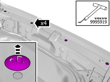
| | Remove the clips.
Use special tool: T9995919, PULLER (SEAL-PINION,CAM-CRANKSHAFT)B200-6304
|
|  | | IMG-383066 |
|
| | |
|  | | IMG-393945 |
|
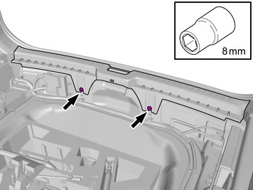
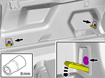
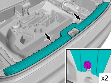
| | Remove the screws.
Tightening torque: Cargo anchor, to body
, 13 Nm
|
|  | | IMG-397295 |
|
| | Repeat on the other side. |
|  | | IMG-383125 |
|
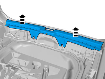
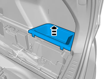
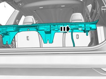
| | Remove the panel. Repeat on the other side. |
|  | | IMG-396625 |
|
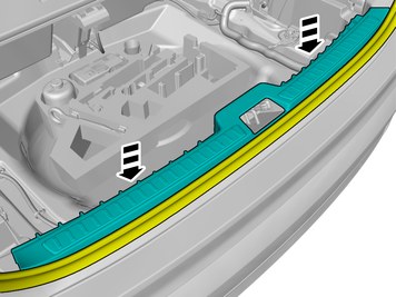
| | Remove the screw. Repeat on the other side. |
| | Vehicles with air suspension |
|  | | IMG-398660 |
|
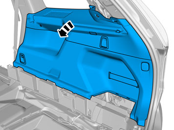
| | Loosen the marked detail. |
|  | | IMG-398661 |
|
| | Disconnect the connector. |
| | |
|  | | IMG-383049 |
|
| | Remove the panel. Disconnect the connectors. |
|  | | IMG-400000 |
|
| | Repeat the steps when removing on opposite side. |
| | |
|  | | IMG-460715 |
|
| | Use detail according to image. |
|  | | IMG-460727 |
|
| | |
|  | | IMG-460735 |
|
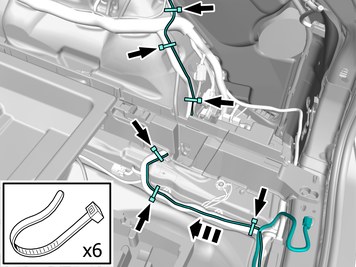
| | Route the wire adjacent to existing wirings. Install the cable. Use a cable tie |
|  | | IMG-460749 |
|
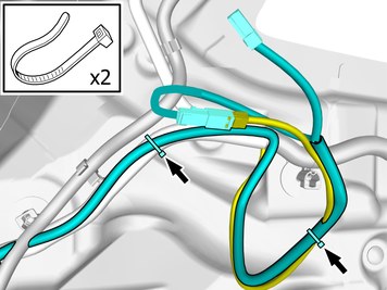
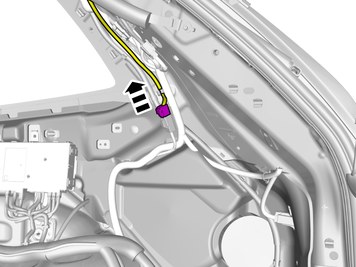
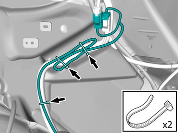
| | Caution!
Do not attach clamb to the sunroof draining hose |
Route the wire adjacent to existing wirings. Install the cable. Use a cable tie |
|  | | IMG-457085 |
|
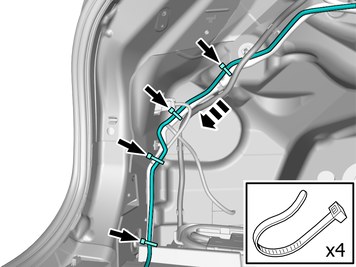
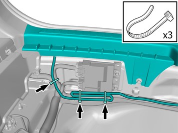
| | Route the wires adjacent to existing wirings. Install the cables. Use a cable tie |
|  | | IMG-441511 |
|
| | Connect the connector. Reinstall the removed part. |
|  | | IMG-457087 |
|
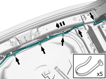
| | Route the wire adjacent to existing wirings. Install the cable. Use a cable tie |
|  | | IMG-457100 |
|
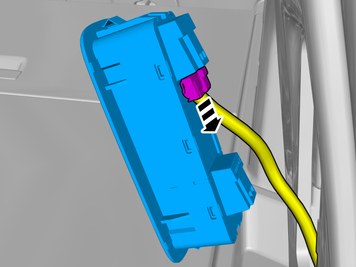
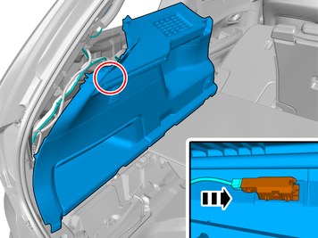
| | Disconnect the connector. |
|  | | IMG-457105 |
|
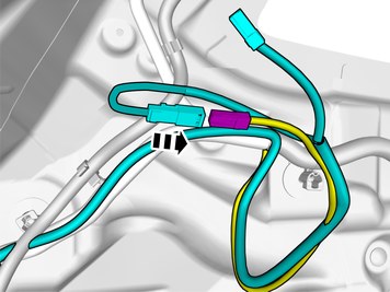
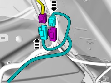
| | Connect the prerouted wiring harness. |
|  | | IMG-457112 |
|
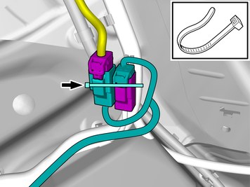
| | Secure the connectors. Use a cable tie |
|  | | IMG-457113 |
|
| | Position the cable harness excess as illustrated. Install the cable. Use a cable tie |
|  | | IMG-441505 |
|
| | Install component that comes with the accessory kit. Connect the connector. |
|  | | IMG-444438 |
|
| | Install the marked component. Make sure that the weather strip goes on top of the panel. Use: Interior trim remover
|
|  | | IMG-444442 |
|
| | |
|  | | IMG-441507 |
|
| | Position the cable harness excess as illustrated. Install the cable. Use a cable tie |
|  | | IMG-441508 |
|
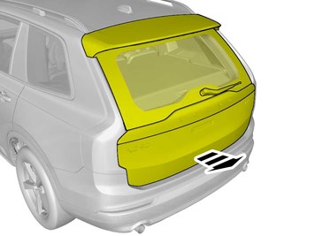
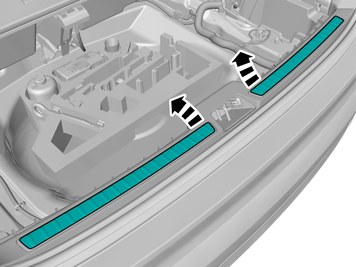
| | Remove the protective film. |
|  | | IMG-442411 |
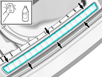
|
| | Remove any traces of glue. Använd en blandning av 50% Volvo koncentrerad spolarvätska och 50% vatten. Repeat on the other side. |
| | |
| | Reinstall the removed parts in reverse order. |