|  | | IMG-262947 |
|
| | Carry out points 1-15 on both sides of the seats. |
|  | | IMG-256044 |
|
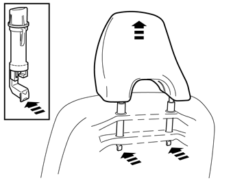
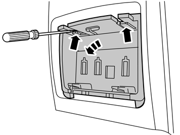
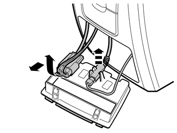
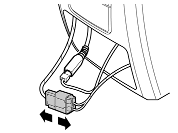
| | Slide the front seat downwards completely at the rear edge. Press the headrest downwards. Find the headrest's two locks on the back of the seat. Press in the catches and pull the headrest upwards at the same time. Disconnect relevant connectors for the telephone.
|
|  | | IMG-262948 |
|
| | |
|  | | IMG-262949 |
|
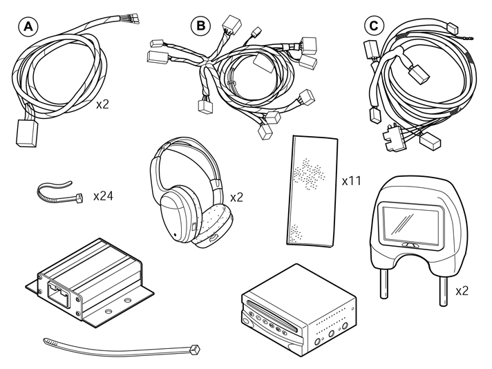
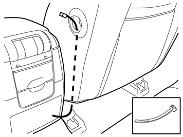
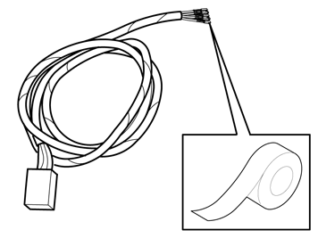
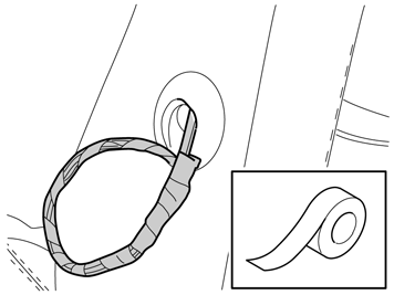
| | Remove cable harness (A) from the kit. First tape the cable terminals together and then secure the cable harness to the cable tie and pull it out by the hole for lumbar support adjustment. Remove the cable tie from the cable harness.
|
|  | | IMG-262950 |
|
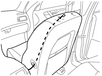
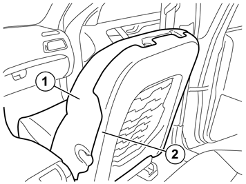
| | Applies to the right-hand front seat Thread the cable tie from the headrest's inner mounting down to the hole for lumbar adjustment. The cable tie must be routed between the upholstery's thin foam and the protective pad (also see image 11).
|
|  | | IMG-262951 |
|
| | |
|  | | IMG-262952 |
|
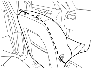
| | Applies to the left-hand front seat. Continue to route the cable under the upholstery and out by the headrest's outer mounting. The cable tie must be routed between the upholstery's thin foam and the protective pad (also see image 11).
|
|  | | IMG-262954 |
|
| | |
|  | | IMG-262953 |
|
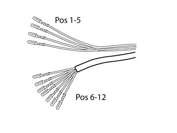
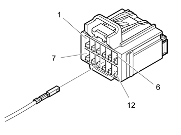
| | Terminal 1-5 - Colour 1 - Black (SB) 2 - Red/White (R/W) 3 - Violet/Grey (VO/GR) 4 - Green (GN) 5 - White (W)
|
|  | | IMG-262955 |
|
| | |
|  | | IMG-262956 |
|
| | 1. Padding 2. Protective pad
|
|  | | IMG-262957 |
|
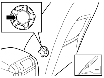
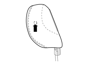
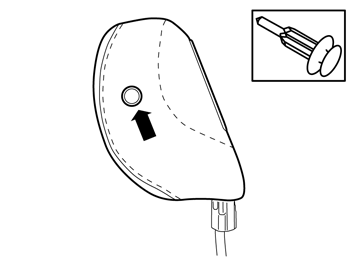
| | Take the headrest from the kit. Locate the hole under the upholstery on the inside of the headrest.
Note!
the inward facing side in the car. |
Make a hole in the upholstery using a scriber or an awl.
|
|  | | IMG-262958 |
|
| | |
|  | | IMG-262959 |
|
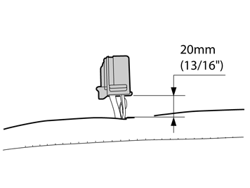
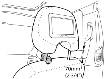
| | Install the headrest on the seat. Only slide it down so that the distance between the seat and lower edge of the headrest is approximately 70mm (2 ¾"). Connect the connector to the headrest. Connect relevant connectors for the telephone.
|
|  | | IMG-262960 |
|
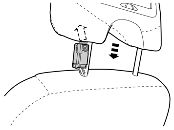
| | Insert the connector diagonally forwards through the hole in the headrest, at the same as moving the headrest down on the seat to the locked position. Check that the headrest is secure by pulling it upwards.
|
|  | | IMG-240984 |
|
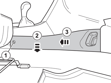
| | Slide the front seats all the way back and then upwards all the way at the front and rear edge. Remove the 2 side panels on the tunnel console by: 1 - turning the clip (1) a quarter turn anti-clockwise. 2 - pulling the panel out by the rear edge. 3 - then pulling the panel backwards until the hooks release. Remove the panel.
|
|  | | M8504883 |
|
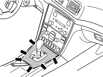
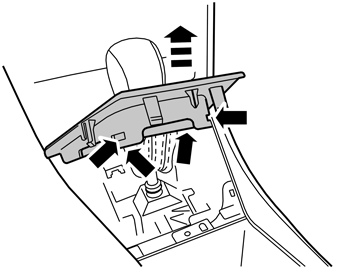
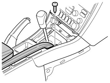
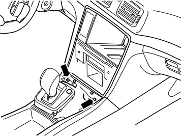
| | Use a plastic weatherstrip tool to detach the gear selector lever panel with boot by carefully prying it off at the rear edge until the two clips release. Pull the panel up until the four clips at the sides have released.
|
|  | | M8504903 |
|
| | |
|  | | IMG-262961 |
|
| | |
|  | | IMG-231616 |
|
| | |
|  | | M8504902 |
|
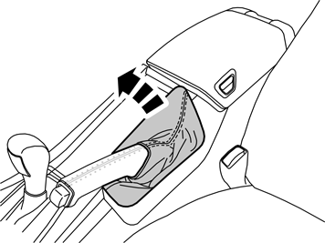
| | Apply the parking brake securely. Shift the gear selector lever to neutral Use a weatherstrip tool to carefully prise up the panel of the handbrake lever boot and remove it. Thread the boot over the parking brake lever.
|
|  | | M8504900 |
|
| | |
|  | | IMG-245980 |
|
| | |
|  | | M8504876 |
|
| | |
|  | | M8504878 |
|
| | |
|  | | IMG-262962 |
|
| | |
|  | | IMG-263744 |
|
| | |
|  | | IMG-231622 |
|
| | |
|  | | IMG-262963 |
|
| | |
|  | | IMG-262964 |
|
| | |
|  | | IMG-241307 |
|
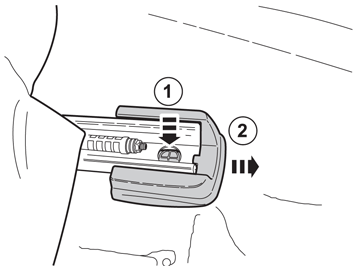
| | Slide the front seats upwards all the way at the front and rear edge. Slide the front seat forward all the way. Remove the two front side pieces from the right-hand seat by pushing down the catches (1) and pulling them straight forward (2). Remove the 2 screws, these will not be reused.
|
|  | | IMG-263014 |
|
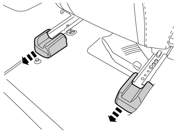
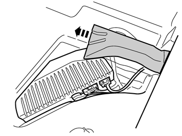
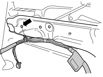
| | Remove the 2 rear seat side pieces by pulling them back. Remove the 2 screws, these will not be reused. Release the seat down. Adjust the angle so that the cable harness to the seat is not stretched.
|
|  | | IMG-245980 |
|
| | |
|  | | IMG-262986 |
|
| | |
|  | | IMG-262987 |
|
| | |
|  | | IMG-262988 |
|
| | |
|  | | IMG-262989 |
|
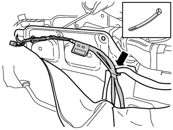
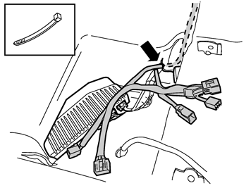
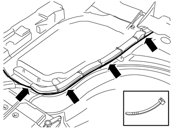
| | Fold the front floor carpet to one side. Lift up the rear floor carpet and continue to route the cable harness next to the amplifier's cable harness. Secure it using a cable tie at the hole in the floor carpet.
|
|  | | IMG-262990 |
|
| | Points 37-43 apply when rear audio separation (RAS box) is to be installed |
|  | | IMG-262991 |
|
| | |
|  | | IMG-262992 |
|
| | |
|  | | IMG-262993 |
|
| | |
|  | | IMG-262994 |
|
| | |
|  | | IMG-262995 |
|
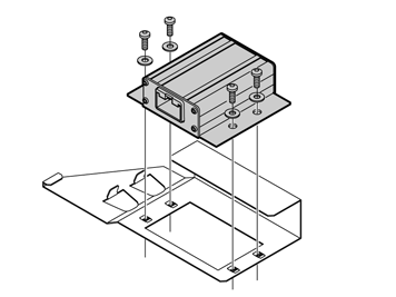
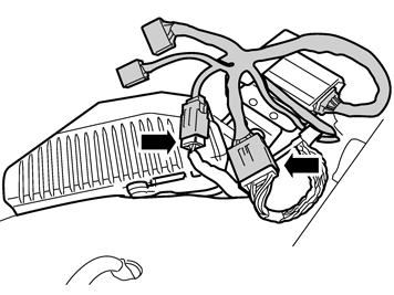
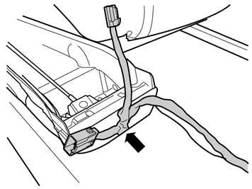
| | Connect the 12 and 2 pin connectors to the cable harness. Take the two large pieces of foam tape from the kit and wrap these around the connectors. Cut off any foam tape excess.
|
|  | | IMG-262996 |
|
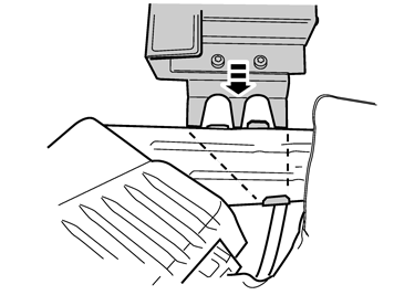
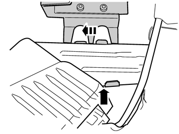
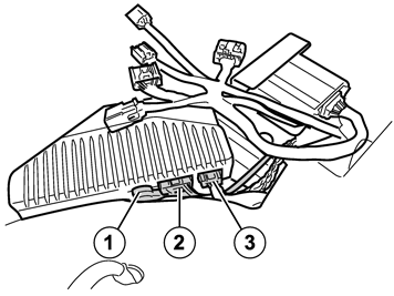
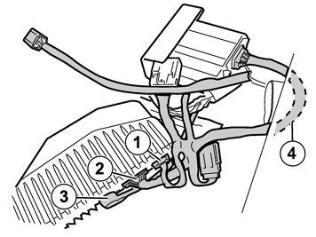
| | Connect the connectors to the amplifier as follows: 1 - 2 pin 2 - 12 pin 3 - DIN connector Place the cable harness excess (4) from the RAS box under the floor carpet and position the connectors and cable harness so that they do not protrude. Reinstall the air blower.
|
|  | | IMG-262997 |
|
| | Points 44-48 apply when a rear audio separation (RAS box) is not to be installed |
|  | | IMG-262998 |
|
| | |
|  | | IMG-262999 |
|
| | |
|  | | IMG-263000 |
|
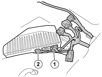
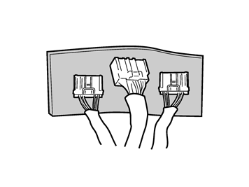
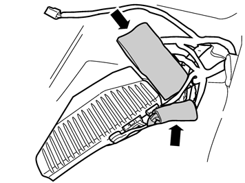
| | Take two large pieces of foam tape from the kit. Attach the 16 pin, green connector and the two 12 pin, grey connectors to one piece of foam tape. Apply the other piece of foam tape on top. Ensure that the green connector's cable terminals are covered by the foam tape.
|
|  | | IMG-263001 |
|
| | |
|  | | IMG-263002 |
|
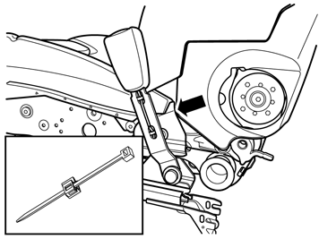
| | Applies to cars without electrically heated seats Take a clip with cable tie from the kit and install it on the plate edge on the left-hand side of the right-hand seat.
|
|  | | IMG-263003 |
|
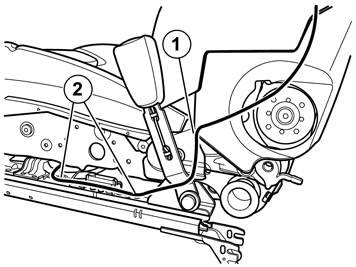
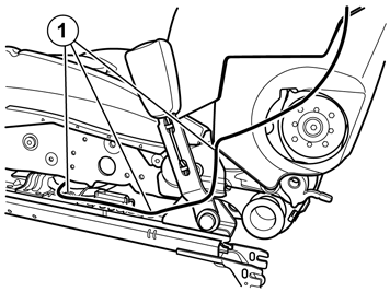
| | Applies to cars without electrically heated seats Take the cable harness from the headrest and pull forward, in underneath the seat. Follow the cable harness for the seat belt buckle. Tighten the cable tie (1). Secure the cable using two cable ties (2).
|
|  | | IMG-263004 |
|
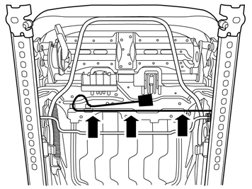
| | Applies to cars with electrically heated seats Take the cable harness from the headrest and pull forward, in underneath the seat. Follow the cable harness for the heating element. Secure the cable using three cable ties (1).
|
|  | | IMG-263005 |
|
| | |
|  | | IMG-263006 |
|
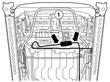
| | Take a piece of foam tape from the kit and cut it in the centre. Fold the seat forward slightly and connect the cable harness from the floor to the connector (1). Tape one cut piece of foam tape around the connectors. Place a cable tie on each side of the connectors and tighten. Fold the seat forward completely.
Note!
Check that the cable harness is not trapped when the seat is slid forwards and backwards. |
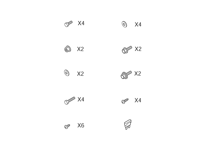
Take 2 sems screw M10x30 and 2 flange screws M10x30 from the kit. Secure the seat at the rear with the sems screws and at the front with the flange screws. Tighten the screws to 40 Nm (29.5 lbf.ft). Reinstall the seat side pieces.
Applies to the passenger seat Fold the backrest forward and backwards and check that the cable harness is not trapped when folding the backrest.
|
|  | | IMG-263007 |
|
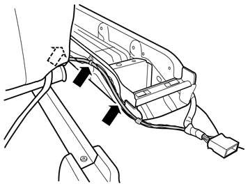
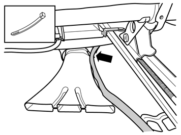
| | Take three cable ties and secure the cable harness at the existing cable harness on the left-hand side of the tunnel console. Route the cable harness forward. Place it in the joint for the floor carpets and out along the air blower.
|
|  | | IMG-263008 |
|
| | |
|  | | IMG-263009 |
|
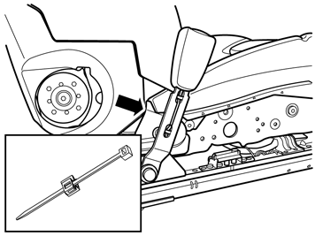
| | Applies to cars without electrically heated seats Take a clip with cable tie from the kit and install it on the plate edge on the right-hand side of the left-hand seat.
|
|  | | IMG-263010 |
|
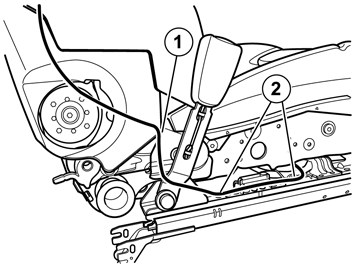
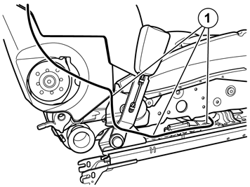
| | Applies to cars without electrically heated seats Take the cable harness from the headrest and pull forward, in underneath the seat. Follow the cable harness for the seat belt buckle. Tighten the cable tie (1). Secure the cable using two cable ties (2).
|
|  | | IMG-263011 |
|
| | Applies to cars with electrically heated seats Take the cable harness from the headrest and pull forward, in underneath the seat. Follow the cable harness for the heating element. Secure the cable using three cable ties (1).
|
|  | | IMG-263012 |
|
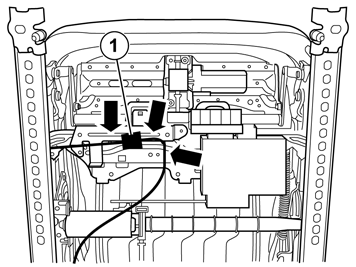
| | Route the cable harness under the seat. Connect the cable harness from the floor to the connector (1). Secure it using a cable tie in the existing cable harness or in a bracket. Tape one cut piece of foam tape around the connectors. Place a cable tie on each side of the connectors and tighten.
Note!
Check that the cable harness is not trapped when the seat is slid forwards and backwards. |
|
|  | | M8803548 |
|
| | |
|  | | M8803356 |
|
| | |
|  | | M8803362 |
|
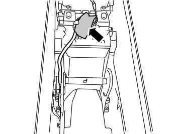
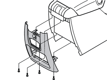
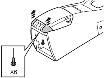
| | Remove the arm rest and covers for the hinge by removing the six screws. The screws, arm rest and covers must not be reused.
|
|  | | IMG-263013 |
|
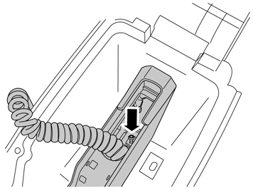
| | For cars with integrated telephone Lift the telephone handset from its cradle. Remove the screw.
|
|  | | IMG-263743 |
|
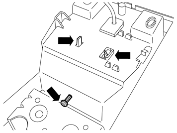
| | For cars with integrated telephone Turn the centre console, remove the screw and remove the two hooks. Remove the handset with holder. Unplug the cable with rubber grommet from the storage compartment.
|
|  | | IMG-263015 |
|
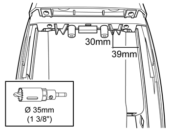
| | Measure the reverse of the tunnel console. From the upper edge of the storage compartment 30mm (1 3/16"). From the inside of the storage compartment's outer edge 39mm (1 9/16"). Pre-drill using a Ø 3mm (7/64") bit. Make the hole using a Ø 35 mm (1 3/8") hole saw. Smooth off the hole edges.
|
|  | | IMG-263016 |
|
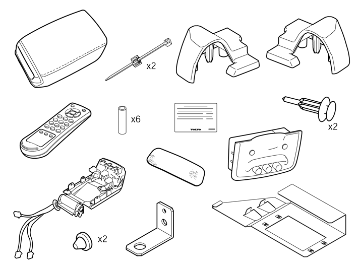
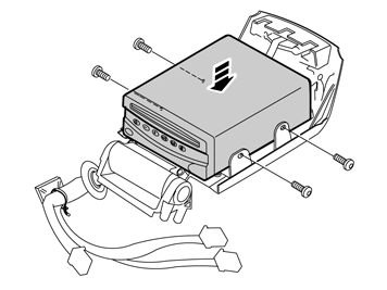
| | Take the lower part of the arm rest, the DVD reader and 4 M4x6 screws from the kit. Connect the connectors and install the DVD reader using the screws.
|
|  | | IMG-263017 |
|
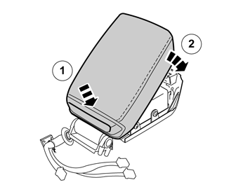
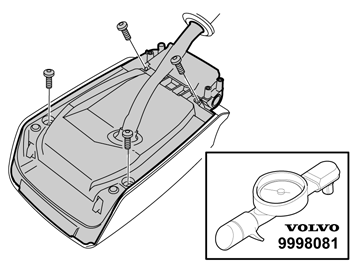
| | Take the cover for the arm rest and 4 screws, PF5x25, from the kit. Install the cover starting at the rear edge.
|
|  | | IMG-263018 |
|
| | |
|  | | IMG-263019 |
|
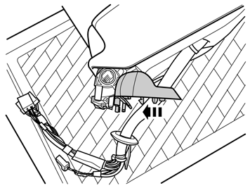
| | Take the two covers for the hinges from the kit. Turn the hinge on the cover so that it corresponds to a cover opening of 45 degrees. Insert the two covers over the hinges.
|
|  | | IMG-263020 |
|
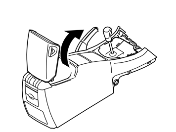
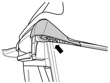
| | Install the cover on the tunnel console. Close the cover so that it locks securely. Guide in the locating pins and hooks for the covers.
|
|  | | IMG-263021 |
|
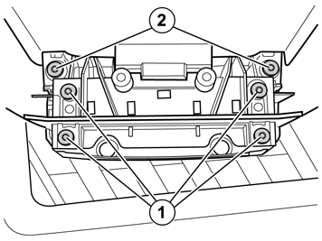
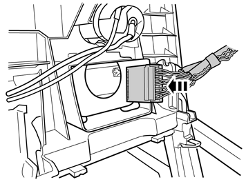
| | Take 6 screws PF5x16 from the kit. Tighten the hinge using 4 screws (1) and torque tighten them to 2.5 Nm (1.84 lbf.ft). Install 2 screws for the covers (2) and torque tighten to 2.5 Nm (1.84 lbf.ft). Ensure that the locating pins and hooks on the covers are inside the walls on the tunnel console whilst tightening. Insert the connectors through the drilled hole in the tunnel console and pull the wiring through up to the rubber grommet.
|
|  | | IMG-263022 |
|
| | |
|  | | IMG-263023 |
|
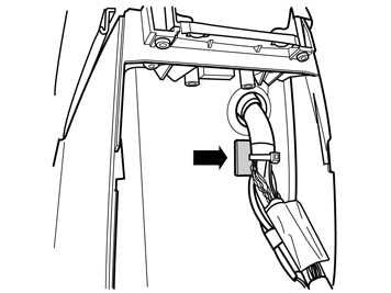
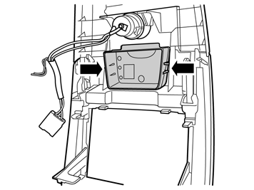
| | Cut off the protective film from the tape on the mounting plate for the wiring. Install the mounting plate 5-10 mm under the outer edge of the rubber grommet on the reverse of the tunnel console. Press the mounting plate securely into position. Check that the rubber grommet's flanges lie correctly against the outside and inside of the plastic walls.
|
|  | | IMG-263024 |
|
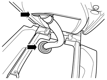
| | Open the armrest's compartment as far as possible (about 70 degree opening). Repeat the 3-4 times and check that the flanges of the rubber grommets do not detach from the tunnel console and lower cover. If necessary, adjust the cable harness in the rubber grommets or mounting plate.
|
|  | | IMG-263025 |
|
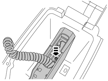
| | For cars with integrated telephone Thread the telephone handset cable through the hole in the storage compartment. Press in the handset holder in the bottom of the storage compartment. Reinstall the 2 screws.
|
|  | | IMG-263026 |
|
| | |
|  | | IMG-263027 |
|
| | |
|  | | IMG-263028 |
|
| | |
|  | | M8502718 |
|
| | |
|  | | M8503121 |
|
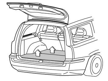
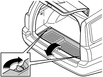
| | Remove the storage box under the rear floor hatch by turning the clips on the right-hand and left-hand sides 90°. Lift it out. Lift out the insulation under the front floor hatch. Also remove the subwoofer, if applicable.
|
|  | | IMG-263029 |
|
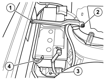
| | Disconnect the battery negative lead. Disconnect the battery positive lead. Slacken off the screw (1) a few turns. Remove the nut (2) and lock brace. Remove the screw (3). Disconnect the vent (4) and remove the battery.
|
|  | | M8502710 |
|
| | |
|  | | IMG-263030 |
|
| | |
|  | | IMG-263031 |
|
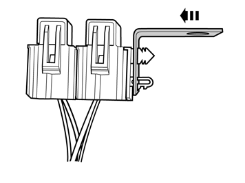
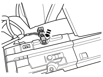
| | Take the bracket and cable harness (C) with the fuse holder from the kit. Press the fuse holder on the bracket. Lift the cover and remove the 5 A fuse temporarily (Small cable).
|
|  | | IMG-263032 |
|
| | |
|  | | IMG-263033 |
|
| | |
|  | | IMG-263034 |
|
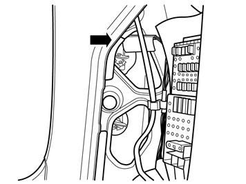
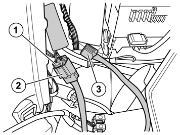
| | Connect the removed connector (1) to the connector (2) on the cable harness. Connect the connector (3) on the cable harness to the tail light. Take a piece of foam tape from the kit and wrap around the connectors (1) and (2).
|
|  | | IMG-263054 |
|
| | |
|  | | IMG-263055 |
|
| | |
|  | | IMG-263056 |
|
| | |
|  | | IMG-263057 |
|
| | |
|  | | M8502823 |
|
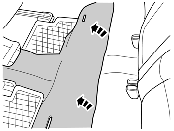
| | Start detaching the sill trim panel by pulling straight up at the rear edge. Continue detaching in the same way along the sill trim panel. Angle out the sill trim panel and remove it. Carry out the procedure on the other side of the car.
|
|  | | IMG-263058 |
|
| | |
|  | | IMG-263059 |
|
| | |
|  | | IMG-263060 |
|
| | |
|  | | IMG-263061 |
|
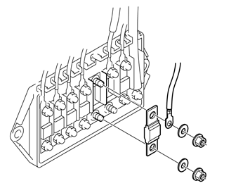
| | Take the fuse, two nuts and two washers from the kit. Install the fuse, cable, washers and nuts. Tighten the nuts. Tighten to 3.5 Nm (2.5 lbf.ft). Reinstall the cover.
|
|  | | IMG-263062 |
|
| | |
|  | | IMG-263063 |
|
| | |
|  | | IMG-263065 |
|
| | |
|  | | IMG-263066 |
|
| | |
|  | | IMG-263068 |
|
| | |
|  | | IMG-263069 |
|
| | |
|  | | IMG-263070 |
|
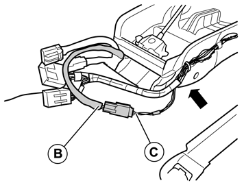
| | Connect the small 3 pin grey connector from the cable harness (B) to corresponding on cable harness (C). Take a piece of foam tape from the kit and cut in the middle. Wrap the foam tape around the connectors. Place the connector under the carpet on the right-hand side of the tunnel console.
|
|  | | IMG-263072 |
|
| | |
|  | | IMG-263073 |
|
| | |
|  | | IMG-263074 |
|
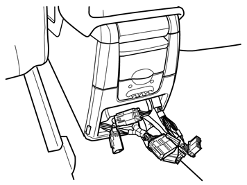
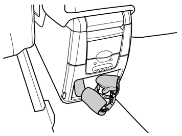
| | Remove the two pieces of foam tape from the kit and cut them in the middle. Connect the 3 pin grey connector from the car's cable harness to corresponding connector on cable harness (C). Wrap one piece of the cut foam tape around the connectors and place these at the lower edge of the opening under the plate flanges. Connect the 3 pin grey connector from the 12 volt socket to the cable harness (C). Wrap one part of the cut foam tape around the connectors and place them on the right-hand side in the opening.
|
|  | | IMG-263076 |
|
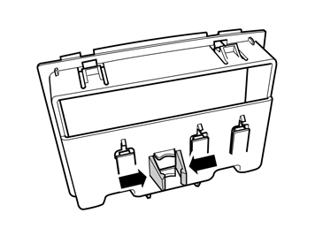
| | Connect the 22 and 10 pin connectors. Take two pieces of foam tape from the kit and wrap each connector with one piece of tape. Cut off any excess. Place the 22 pin connector at the upper edge of the opening, on the left. Place the 10 pin connector in the middle of the upper edge opening.
For cars with integrated telephone Wrap one cut piece of foam tape around the connectors. Place these at the lower edge of the opening
|
|  | | IMG-263077 |
|
| | |
|  | | IMG-242267 |
|
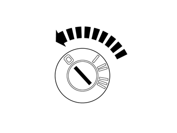
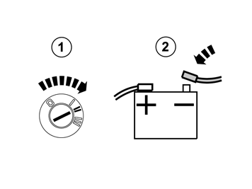
| | Reinstall the battery, the lock braces and vents. Reconnect the battery positive lead. Turn the ignition key to position II. Reconnect the battery negative lead. Reinstall the 5 A fuse. Turn the ignition key to position 0 and then back to position II. Wait for the "parking brake" indicator lamp to go out in the combined instrument panel. Then apply the parking brake. The indicator lamp in the combined instrument panel must light when the parking brake is applied. Release the parking brake. The indicator lamp in the combined instrument panel must go out.
In the cargo compartment, reinstall: the insulation panel. subwoofer, if applicable. the cargo box. side panels. floor hatches.
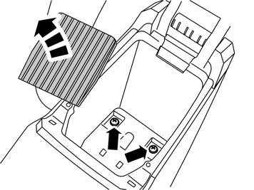
In the passenger compartment, reinstall: the sill trim panels. the cushion supports. the rear seat cushions with catches. the side panels on the tunnel console. the screw at the front edge of the handle (XC70). the panel for the gear lever. the rubber mat in the storage compartment. the parking brake lever panel and remove the protective tape.
Install batteries in the remote control and headsets. Region code the DVD player. Information is in VIDA under: Product specifications / Design and function / 39 Media, communication and navigation / 393 equipment for entertainment (radio/TV/VCR) / System for rear seat entertainment/ Design
|
|  | | IMG-263078 |
|
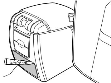
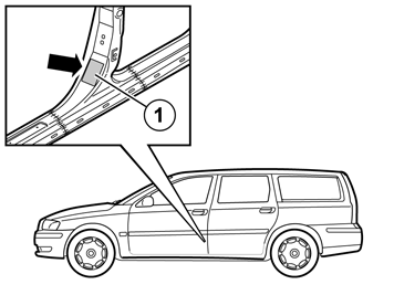
| | Take the black decal from the kit. Clean the area (1) where the decal will be located. Use a mixture of 30% windscreen washer fluid and 70% water. Wipe dry. Remove the backing paper from the adhesive side of the decal. Secure the decal as illustrated. Press the decal into place properly.
|

