| | |
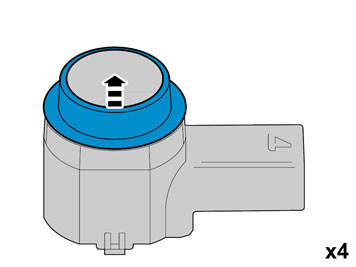
| | NOTE! During installation the car and parts must maintain a temperature of at least +20° (68° F). |
|  | | IMG-344336 |
|
| | |
|  | | IMG-352653 |
|
| | |
|  | | IMG-352654 |
|
| | |
| | | IMG-352653 |
|
| | |
|  | | IMG-352655 |
|
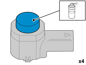
| | Caution!
Protect the connections' contact surfaces against paint. |
Paint the sensors in the same colour code as the vehicle. Use Volvo Touch-up paint. (Only use base coat.) Use: Volvo 2-K Varnish. P/N: 31335447
Note!
Also read the instructions on the spray can. |
|
|  | | IMG-352658 |
|
| | Caution!
The paint must have dried after the first application. |
|
|  | | R8503999 |
|
| | Applies to cars with two rows of seats Fold up the middle, rear floor hatch. Unhook the straps. Remove the storage box underneath and lift it out. Fold back the floor hatch. Pull the floor hatch backwards and lift it out.
Applies to cars with three rows of seats and integrated carrier bag holder on the underside of the floor hatch Fold up the floor hatch. Detach the two straps on the panel under this. Lift up the rear edge of the panel, fold the floor hatch back towards the panel and lift out the floor hatch with the panel.
Applies to cars with three rows of seats without an integrated carrier bag holder Fold up the floor hatch at the rear edge and lift it out.
|
|  | | R3100130 |
|
| | |
|  | | IMG-246024 |
|
| | |
|  | | R3100131 |
|
| | Remove the pre-punched pieces (1) from the insulation panel in the rear crossmember by cutting them off at the markings. Remove the four sleeve nuts holding the bumper in place. They are in the holes under the insulation panel. Lift them out and remove them using a magnet
|
|  | | R8600873 |
|
| | |
|  | | IMG-246025 |
|
| | |
|  | | R8600883 |
|
| | |
|  | | IMG-246027 |
|
| | Applies to cars with mudguards Drill out the two rivets using a 6 mm (1/4") drill bit. Leave the inner rivet in place. Turn the mud guard outwards/downwards. Repeat on opposite side.
|
|  | | IMG-246028 |
|
| | |
|  | | IMG-246123 |
|
| | Grasp the lower edge of the upper section of the bumper cover. Pull straight out so that the three hooks release. The hooks may be hard to release, if so, release using a weatherstrip tool. Pull out the ends further until the four hooks, which are horizontally positioned at the upper edge, release. Repeat on opposite side.
|
|  | | IMG-246029 |
|
| | Fold up the lower tailgate. Pull the bumper backwards and remove the bumper. Place the bumper on a suitable surface that will not damage the paint. Remove the remaining parts of the removed rivets.
|
|  | | IMG-246030 |
|
| | |
|  | | IMG-246045 |
|
| | Unhook the ten catches at the upper edge of the bumper. Release the nine hooks in the middle of the bumper, at the same time as separating the inner and outer sections of the bumper. Remove the inner part of the bumper.
|
|  | | IMG-246046 |
|
| | |
|  | | IMG-246047 |
|
| | |
|  | | IMG-246048 |
|
| | |
| | Installing the bumper section with sensors |
|  | | IMG-246049 |
|
| | Installing the bumper section with sensors Note!
Do not damage the painted surface. |
|
|  | | IMG-246052 |
|
| | Press the cable harness connectors into the sensor's connectors. A clicking noise should be heard, which confirms that the catches have activated. Press the sensors with cable harness in each holder with the connector pointing to the left, as illustrated.
|
|  | | IMG-246053 |
|
| | |
|  | | IMG-246054 |
|
| | |
|  | | IMG-246055 |
|
| | |
|  | | IMG-246056 |
|
| | |
|  | | IMG-246057 |
|
| | |
| | |
|  | | IMG-246058 |
|
| | |
|  | | IMG-246059 |
|
| | |
|  | | R8903013 |
|
| | |
|  | | IMG-246060 |
|
| | Fold up the lower tailgate. Lift up the bumper, insert the cable from the sensors into the large rectangular hole to the left in the rear crossmember, and then into the hole where the foam seal was located.
|
|  | | IMG-246061 |
|
| | Position the cable in its cutout between the plastic bracket and the bumper cover. Check that the guide on the side of the bumper cover is inside the plastic bracket. Press the bumper's four hooks at the rear edge into place. Press all the hooks for the ends into the body. Lower the lower tailgate. Tighten the bumper using the four sleeve nuts. Tighten to 16 Nm (12 lbf.ft.).
Hint
To facilitate installation, secure the sleeve nut to the tool using butyl tape. |
Take the new pieces of insulation panel and place them over the holes for the bumper. Connect the connector to the fog lamp. Reinstall the cover panels under the tail lamps. Rivet the bumper at the rear edge of the wheel housing, on both sides. Use rivets from the kit. Turn back and rivet any mud guards.
|
| | Installation of the control module (PAM) |
|  | | R8504475 |
|
| | Installation of the control module (PAM) |
|  | | IMG-246062 |
|
| | |
|  | | IMG-222282 |
|
| | |
|  | | IMG-246063 |
|
| | |
|  | | IMG-246064 |
|
| | |
|  | | IMG-246065 |
|
| | Remove the protective film from the Velcro tape. Press the control module properly onto the flat surface behind the panel, as illustrated. The control module's left end must be edge to edge with the panel reinforcement's vertical edge.
|
| | |
|  | | R3904120 |
|
| | |
| | |
|  | | R8504177 |
|
| | |
|  | | R8504178 |
|
| | Carefully pull out the surround using the scriber along the underneath of the surround. The surround is secured by three mounting lugs at the upper and lower edges. Do not damage the surround. Place the surround to one side.
Hint
A surround with four button locations can be replaced with a surround with seven button locations if required. This is available for purchasing separately. |
|
|  | | D8502226 |
|
| | |
| | |
|  | | IMG-246103 |
|
| | Turn the ignition key to position II. Reconnect the battery negative lead Reinstall the cover and holder for the battery. Reinstall the holder for the tool bag. Reinstall the side compartment and floor hatches.
|
|  | | IMG-242268 |
|
| | Download software (application) for the accessory's function according to service information in VIDA. See VIDA or accessories catalogue for article number on software. |