| | |
| | Read through all of the instructions before starting installation. Notifications and warning texts are for your safety and to minimise the risk of something breaking during installation. Ensure that all tools stated in the instructions are available before starting installation. Certain steps in the instructions are only presented in the form of images. Explanatory text is also given for more complicated steps. In the event of any problems with the instructions or the accessory, contact your local Volvo dealer.
|
| | |
|  | | IMG-363036 |
|
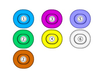
| | Note!
This colour chart displays (in colour print and electronic version) the importance of the different colours used in the images of the method steps. |
Used for focused component, the component with which you will do something. Used as extra colors when you need to show or differentiate additional parts. Used for attachments that are to be removed/installed. May be screws, clips, connectors, etc. Used when the component is not fully removed from the vehicle but only hung to the side. Used for standard tools and special tools. Used as background color for vehicle components.
|
| | Vehicles with parking assistance |
|  | | IMG-400006 |
|
| | Download software (application) for the accessory's function according to the service information in VIDA. Order and download software according to: 32259057
|
| | Vehicles with Foot movement detection (FMDM) |
| | | IMG-400006 |
|
| | Download software (application) for the accessory's function according to the service information in VIDA. Order and download software according to: 31664327
|
| | |
|  | | IMG-438250 |
|
| | |
|  | | IMG-438251 |
|
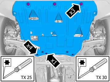
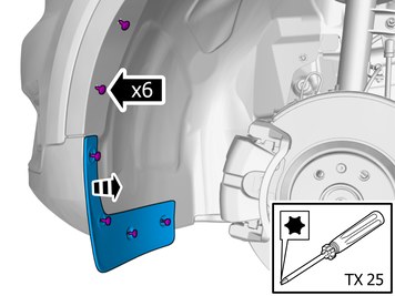
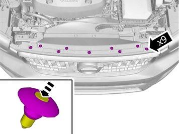
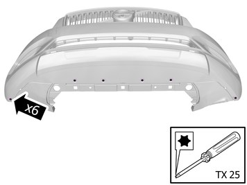
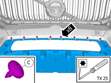
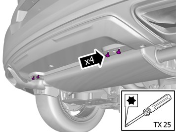
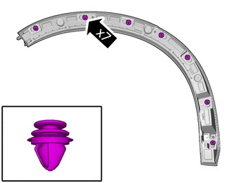
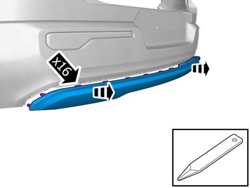
| | Remove the screws. Remove the clip. Remove the marked part. |
|  | | IMG-452926 |
|
| | |
|  | | IMG-403425 |
|
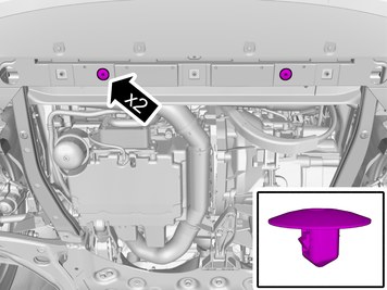
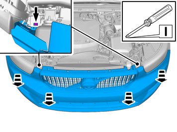
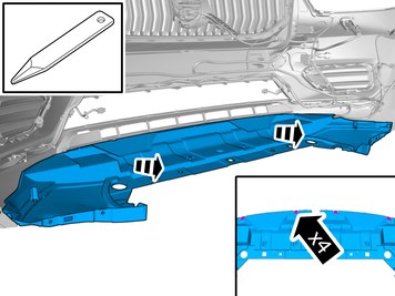
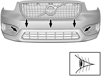
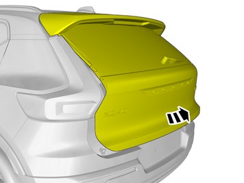
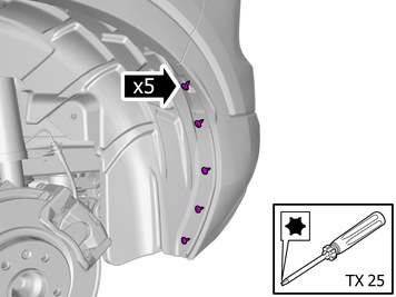
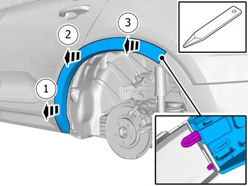
| | Remove the marked detail/details. |
|  | | IMG-415975 |
|
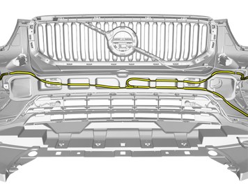
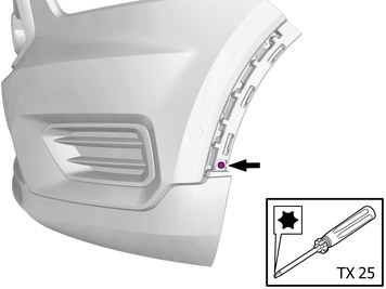
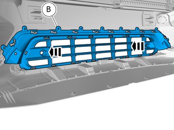
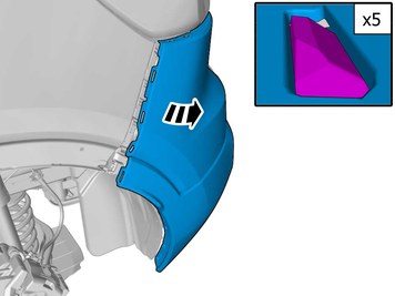
| | Remove the marked detail/details. |
|  | | IMG-438237 |
|
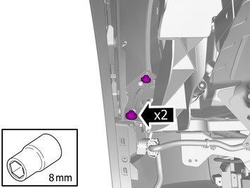
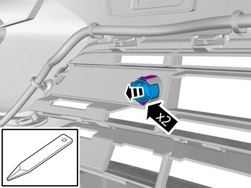
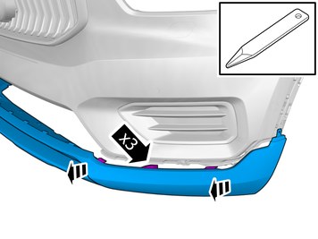
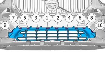
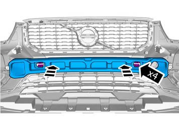
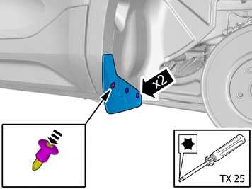
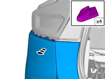
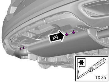
| | Remove the screws. Remove the marked part. |
|  | | IMG-438238 |
|
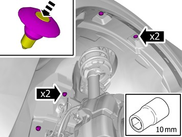
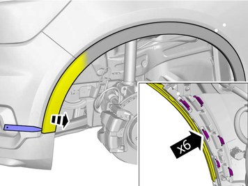
| | Remove the nuts. Remove the clips. |
|  | | IMG-438245 |
|
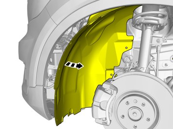
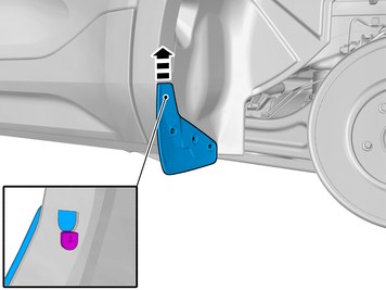
| | Fold the wing liner aside. |
|  | | IMG-438247 |
|
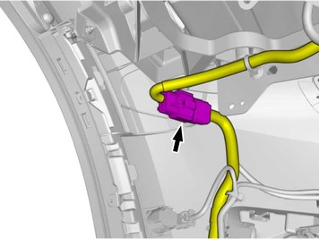
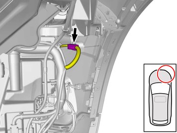
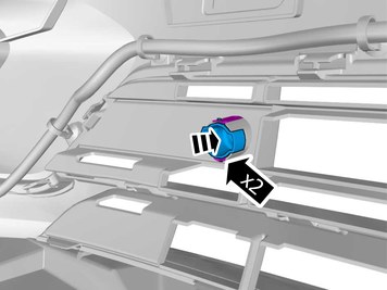
| | Disconnect the connector. |
|  | | IMG-438252 |
|
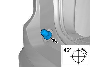
| | Caution!
Make sure not to damage painted surfaces. |
Loosen the component indicated. Do not remove it. |
|  | | IMG-438248 |
|
| | |
| | Repeat the steps when removing on opposite side. |
|  | | IMG-438249 |
|
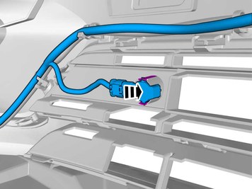
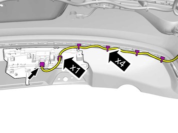
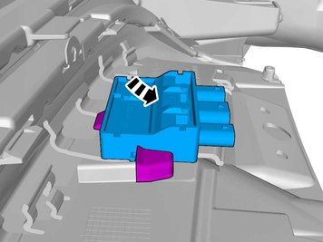
| | Note!
The number of connectors may vary depending on the vehicle's equipment level. |
Disconnect the connector. |
|  | | IMG-438350 |
|
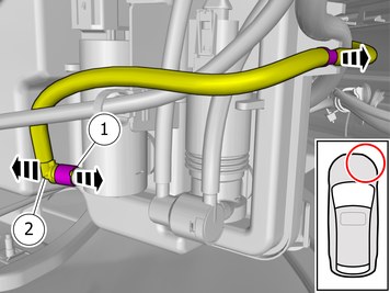
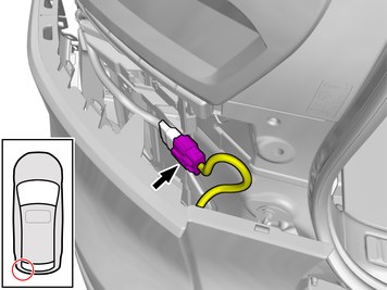
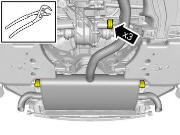
| | Warning!
Be prepared to collect escaping fluid. |
Release the lock. Undo the hose from the connection.
|
|  | | IMG-438260 |
|
| | |
|  | | IMG-438263 |
|
| | Caution!
Place the Bumper Cover on a suitable surface. |
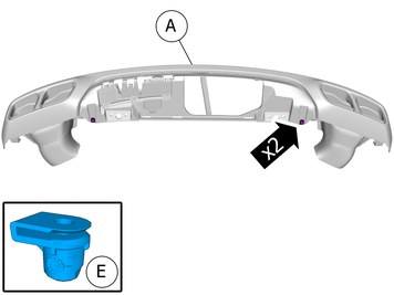
Request the aid of a colleague for this procedure. Remove the marked part. |
|  | | IMG-438264 |
|
| | |
|  | | IMG-438265 |
|
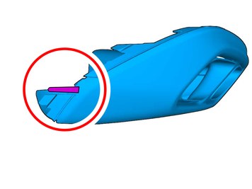
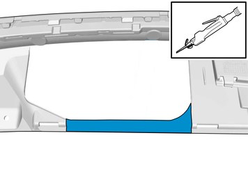
| | Release the catches. Remove the marked part. |
|  | | IMG-438276 |
|
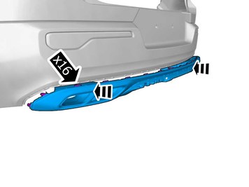
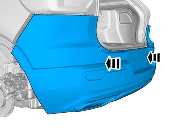
| | Release the catches. Remove the marked part. The part is to be reused. Repeat on the other side. |
|  | | IMG-438280 |
|
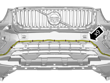
| | Remove the cable harness clips. Fold marked part aside. |
| | Vehicles with parking assistance |
|  | | IMG-439800 |
|
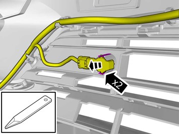
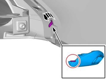
| | Release the catches. Fold marked part aside. |
|  | | IMG-438282 |
|
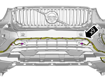
| | Remove the cable harness clips. Fold marked part aside. |
| | |
|  | | IMG-438283 |
|
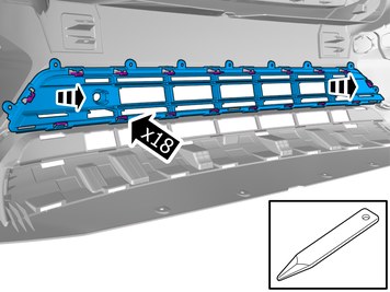
| | Release the catches. Remove the marked part. |
|  | | IMG-438275 |
|
| | |
|  | | IMG-438285 |
|
| | Release the catches. Remove the marked part. |
|  | | IMG-438286 |
|
| | Remove the screw. Repeat on the other side. |
|  | | IMG-438287 |
|
| | Remove the marked part. Repeat on the other side. |
| | |
|  | | IMG-439823 |
|
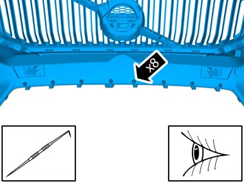
| | Locate relevant marking. Mark the centre. |
|  | | IMG-438290 |
|
| | |
|  | | IMG-439810 |
|
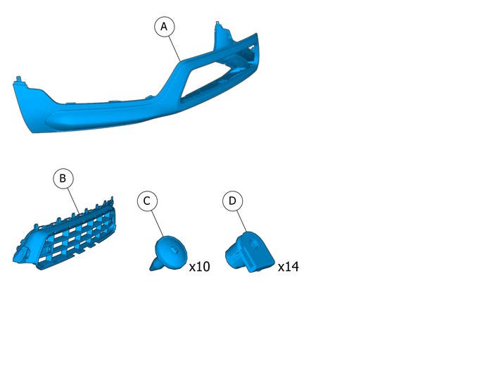
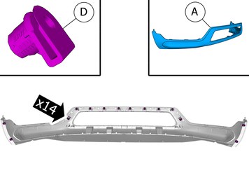
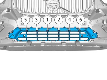
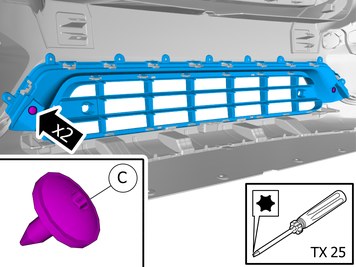
| | Install components that come with the accessory kit. Install the clip(s). |
|  | | IMG-438371 |
|
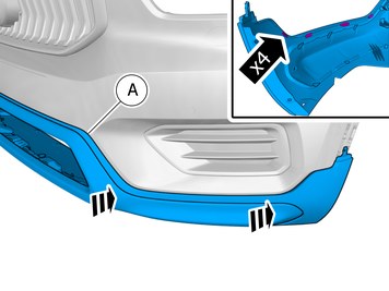
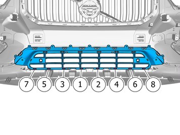
| | Install component that comes with the accessory kit. Ensure that all clips engage. Repeat on the other side. |
|  | | IMG-438378 |
|
| | |
|  | | IMG-451690 |
|
| | Note!
Adjust the position of the components to create even spaces. |
|
| | | IMG-438286 |
|
| | Install the screw. Repeat on the other side. |
|  | | IMG-438372 |
|
| | Install component that comes with the accessory kit. |
|  | | IMG-450094 |
|
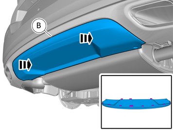
| | Note!
Make sure to follow the sequence indicated. |
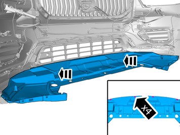
Press the marked component. Ensure that all clips engage. |
|  | | IMG-450103 |
|
| | Note!
Make sure to follow the sequence indicated. |
Press the marked component. Ensure that all clips engage. |
|  | | IMG-450104 |
|
| | Note!
Make sure to follow the sequence indicated. |
Press the marked component. Ensure that all clips engage. |
|  | | IMG-438381 |
|
| | |
| | |
|  | | IMG-438315 |
|
| | Install the marked component. Ensure that all clips engage. |
| | | IMG-438275 |
|
| | |
| | | IMG-438280 |
|
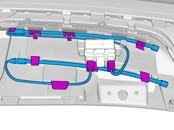
| | Fasten the wiring harness using the existing clips. |
|  | | IMG-438325 |
|
| | Install the marked component. Repeat on the other side. |
| | Vehicles with parking assistance |
| | | IMG-438282 |
|
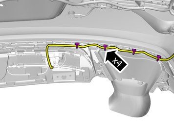
| | Fasten the wiring harness using the existing clips. |
|  | | IMG-439803 |
|
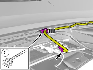
| | Install the marked component. Ensure that all clips engage. Repeat on the other side. |
| | |
|  | | IMG-438327 |
|
| | Install the marked component. |
| | Reinstall the removed parts in reverse order. |
|  | | IMG-405228 |
|
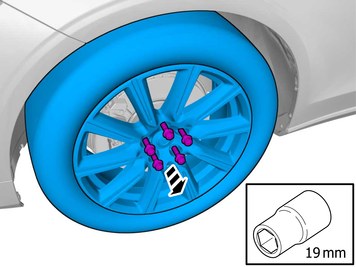
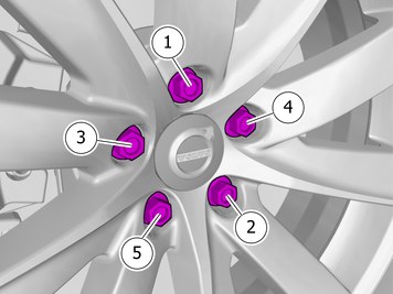
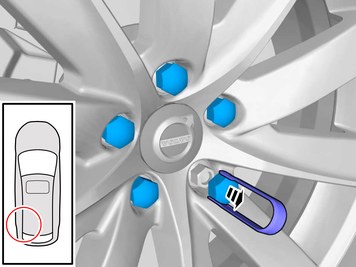
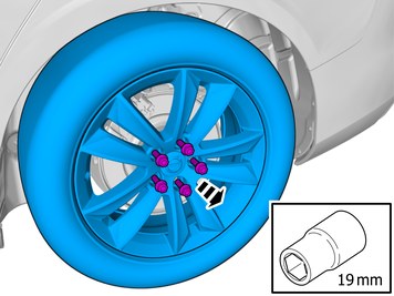
| |
Tightening torque: Aluminum wheel rim to wheel hub
Stage 1:
4 Nm
Stage 2:
50 Nm
Stage 3:
140 Nm
|
| | |
|  | | IMG-435728 |
|
| | |
|  | | IMG-435791 |
|
| | Make sure that the components are not mixed up at the installation. Remove the marked part. |
|  | | IMG-440049 |
|
| | |
|  | | IMG-446456 |
|
| | Remove the marked detail/details. |
|  | | IMG-441820 |
|
| | Remove the marked detail/details. |
|  | | IMG-446440 |
|
| | |
|  | | IMG-446442 |
|
| | Remove the screws. Remove the clip. |
|  | | IMG-446443 |
|
| | |
|  | | IMG-446444 |
|
| | Note!
The graphic shows the back of the component before removal. |
|
|  | | IMG-446445 |
|
| | Caution!
Make sure not to damage painted surfaces. |
Remove the marked part. Use: Interior trim remover
|
|  | | IMG-446446 |
|
| | Caution!
Be extra careful when removing or installing this component. |
Loosen the component indicated. Do not remove it. |
|  | | IMG-446447 |
|
| | Loosen the component indicated. Do not remove it. |
| | Repeat the steps when removing on opposite side. |
|  | | IMG-446957 |
|
| | Locate the connector. Disconnect the connector. |
|  | | IMG-446948 |
|
| | Caution!
Place the Bumper Cover on a suitable surface. |
Request the aid of a colleague for this procedure. Remove the marked part. |
| | Vehicles with Foot movement detection (FMDM) |
|  | | IMG-452940 |
|
| | Disconnect the connector. Loosen the clips. Fold marked part aside. |
|  | | IMG-446786 |
|
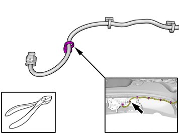
| | Remove the clip. Use: Pliers
|
|  | | IMG-440188 |
|
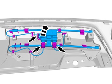
| | Disconnect the connectors. Release the catches. Remove the marked detail/details. The part is to be reused. |
| | |
|  | | IMG-446867 |
|
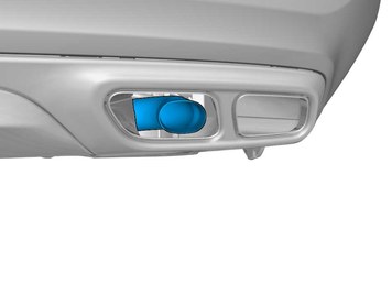
| | Release the catches. Remove the marked part. |
|  | | IMG-451405 |
|
| | Remove the screws. The part is not to be reused. |
|  | | IMG-451537 |
|
| | |
| | Vehicles with gasoline engines |
|  | | IMG-451756 |
|
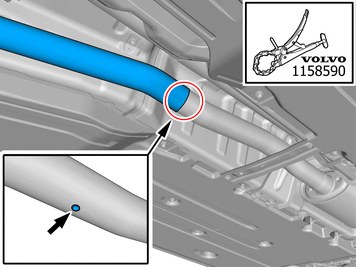
| | Locate relevant marking. Remove the marked part.
Use special tool: T1158590, PIPE CUTTER
|
|  | | IMG-451184 |
|
| | Note!
This step is easier with two people. |
Fold marked part aside. |
|  | | IMG-451415 |
|
| | |
| | Vehicles with diesel engines |
|  | | IMG-451227 |
|
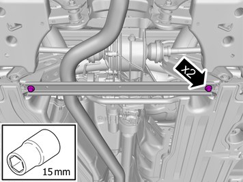
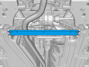
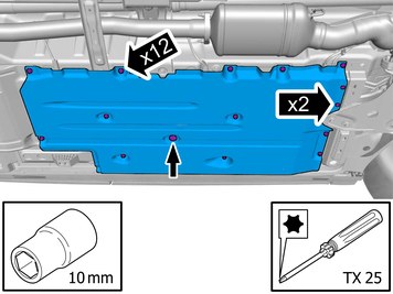
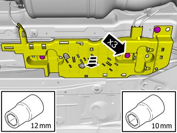
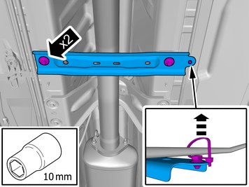
| | Remove the screws. Remove the nuts. Remove the clip. Remove the marked part. |
|  | | IMG-451316 |
|
| | Remove the screws. Fold marked part aside.
Tightening torque: M8
, 24 Nm
|
|  | | IMG-451305 |
|
| | Remove the cable harness clips. Remove the marked part. |
|  | | IMG-451318 |
|
| | Remove the screws. Fold marked part aside.
Tightening torque: M8
, 24 Nm
|
|  | | IMG-451342 |
|
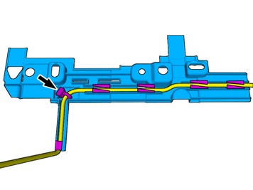
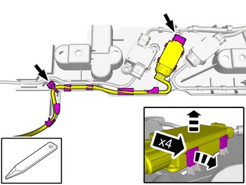
| | Disconnect the connector. Remove the cable harness clips. Fold marked part aside. |
|  | | IMG-451392 |
|
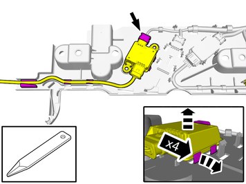
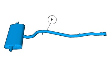
| | Disconnect the connector. Remove the cable harness clips. Fold marked part aside. |
|  | | IMG-451385 |
|
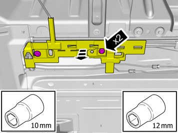
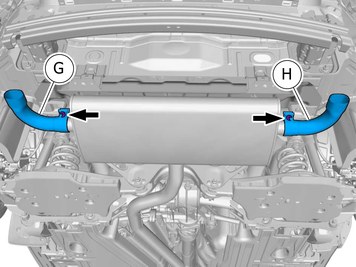
| | Remove the nuts. Fold marked part aside. |
|  | | IMG-451401 |
|
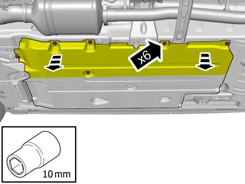
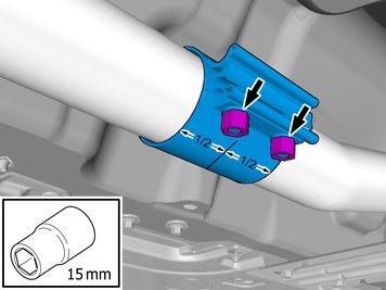
| | Loosen the clip. Remove the screws.
Tightening torque: M8
, 24 Nm
Remove the marked part. |
|  | | IMG-451410 |
|
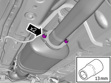
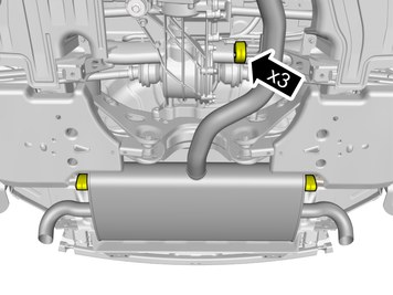
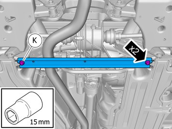
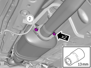
| | Remove the nuts. The part is not to be reused. |
| | | IMG-451184 |
|
| | Note!
This step is easier with two people. |
Fold marked part aside. |
| | | IMG-451415 |
|
| | |
|  | | IMG-451532 |
|
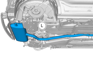
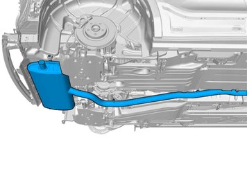
| | Remove the marked part. The part is not to be reused. |
|  | | IMG-451492 |
|
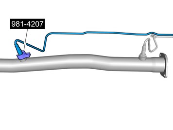
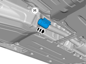
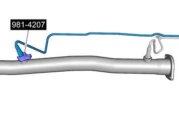
| | Remove the marked part.
Use special tool: T9814207, Crow foot
The part is to be reused. |
|  | | IMG-451494 |
|
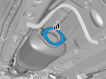
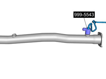
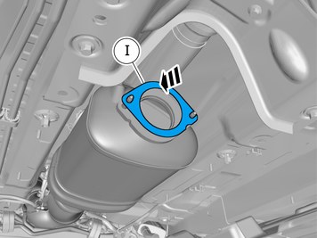
| | Remove the marked part.
Use special tool: T9995543, Socket NV-22 (heated oxygen sensor)
The part is to be reused. |
| | |
| | Vehicles with gasoline engines |
|  | | IMG-451765 |
|
| | Note!
Do not fully tighten the nuts yet. |
Install component that comes with the accessory kit. |
|  | | IMG-451767 |
|
| | Note!
This step is easier with two people. |
Install component that comes with the accessory kit. |
|  | | IMG-451768 |
|
| | Install the marked components. |
|  | | IMG-451770 |
|
| | Place the component where indicated in the graphic. Tighten the nuts.
Tightening torque: M10
, 50 Nm
|
|  | | IMG-451559 |
|
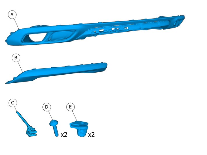
| | Reinstall the removed part. Install components that come with the accessory kit.
Tightening torque: Reinforcement bar, to subframe rear
Stage 1:
90 Nm
Stage 2:
30 Degree
|
|  | | IMG-451616 |
|
| | Note!
Do not fully tighten the nuts yet. |
Install components that come with the accessory kit. |
| | Vehicles with diesel engines |
|  | | IMG-451527 |
|
| | Use detail according to image. |
|  | | IMG-451498 |
|
| | Reinstall the removed part.
Use special tool: T9995543, Socket NV-22 (heated oxygen sensor)
Tightening torque:
,
|
|  | | IMG-451500 |
|
| | Reinstall the removed part.
Use special tool: T9814207, Crow foot
Tightening torque:
,
|
|  | | IMG-451541 |
|
| | Install component that comes with the accessory kit. |
|  | | IMG-451553 |
|
| | Install component that comes with the accessory kit. |
| | | IMG-451768 |
|
| | Install the marked components. |
|  | | IMG-451555 |
|
| | Install components that come with the accessory kit. Tighten the nuts.
Tightening torque: M8
, 24 Nm
|
| | | IMG-451559 |
|
| | Reinstall the removed part. Install components that come with the accessory kit.
Tightening torque: Reinforcement bar, to subframe rear
Stage 1:
90 Nm
Stage 2:
30 Degree
|
| | | IMG-451616 |
|
| | Note!
Do not fully tighten the nuts yet. |
Install components that come with the accessory kit. |
| | Reinstall the removed parts in reverse order. |
| | |
|  | | IMG-447725 |
|
| | Install components that come with the accessory kit. |
|  | | IMG-450115 |
|
| | Caution!
Be extra careful when removing or installing this component. |
Caution!
Make sure not to damage painted surfaces. |
|
|  | | IMG-446879 |
|
| | Request the aid of a colleague for this procedure. Install component that comes with the accessory kit. Ensure that all clips engage. |
|  | | IMG-446881 |
|
| | Note!
Fold the marked component properly around the edge. |
|
| | Vehicles with Foot movement detection (FMDM) |
|  | | IMG-446890 |
|
| | Reinstall the removed part. |
|  | | IMG-446900 |
|
| | Caution!
Make sure to place the component as the graphic shows. |
Reinstall the removed part. Connect the connectors. |
|  | | IMG-446940 |
|
| | Fasten the wiring harness using the existing clips. |
|  | | IMG-446941 |
|
| | Connect the connector. Install component that comes with the accessory kit. |
| | Vehicles with folding towbar |
|  | | IMG-447012 |
|
| | |
|  | | IMG-440798 |
|
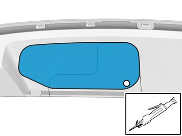
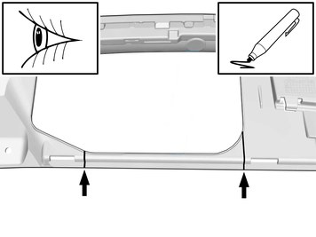
| | Locate relevant marking. Mark using a pen |
|  | | IMG-440814 |
|
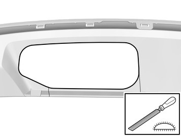
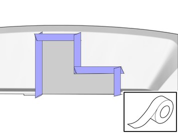
| | Apply tape to the other side, opposite the marking lines. Use: , Masking tape
|
|  | | IMG-440802 |
|
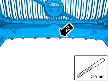
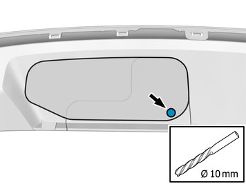
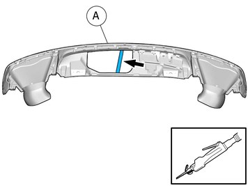
| | Make a hole, using the tool indicated. |
|  | | IMG-440804 |
|
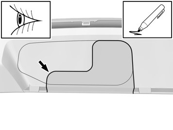
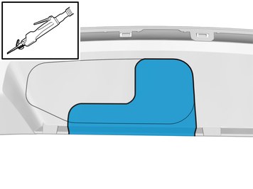
| | Remove the marked part. Use: Air-powered air saw
|
|  | | IMG-440805 |
|
| | |
|  | | IMG-447010 |
|
| | Remove the marked part. Use: Air-powered air saw
|
| | Vehicles with towbar, Hitch |
| | | IMG-447012 |
|
| | |
|  | | IMG-440821 |
|
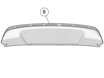
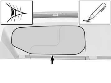
| | Locate relevant marking. Mark using a pen |
|  | | IMG-440831 |
|
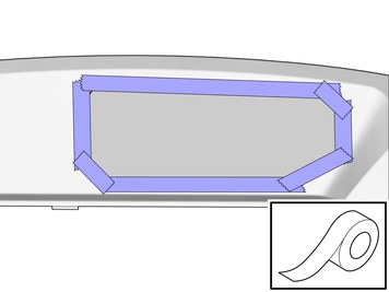
| | Apply tape to the other side, opposite the marking lines. Use: , Masking tape
|
|  | | IMG-440816 |
|
| | Remove the marked part. Use: Air-powered air saw
|
|  | | IMG-440835 |
|
| | |
| | | IMG-447010 |
|
| | Remove the marked part. Use: Air-powered air saw
|
|  | | IMG-440846 |
|
| | Locate relevant marking. Mark using a pen |
|  | | IMG-440839 |
|
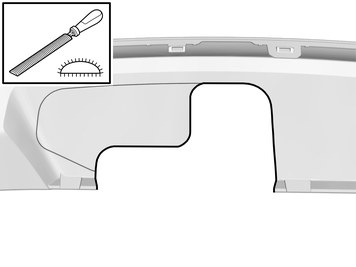
| | Remove the marked part. Use: Air-powered air saw
|
|  | | IMG-440860 |
|
| | |
| | |
| | | IMG-446957 |
|
| | |
|  | | IMG-446949 |
|
| | Request the aid of a colleague for this procedure. Connect the connector. Reinstall the removed part. |
|  | | IMG-446961 |
|
| | |
|  | | IMG-446962 |
|
| | Install component that comes with the accessory kit. Ensure that all clips engage. |
|  | | IMG-446995 |
|
| | Install component that comes with the accessory kit. Tighten the bolts. |
|  | | IMG-451639 |
|
| | |
|  | | IMG-451849 |
|
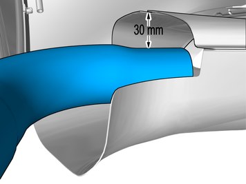
| | Adjust to the specified value. Repeat on the other side. |
|  | | IMG-451636 |
|
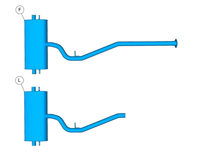
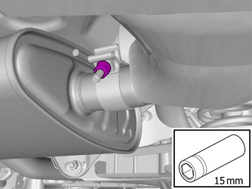
| | Tighten the nut.
Tightening torque: Exhaust end pipe, to Muffler
, 55 Nm
Repeat on the other side. |
| | |
| | Reinstall the removed parts in reverse order. |
| | | IMG-405228 |
|
| |
Tightening torque: Aluminum wheel rim to wheel hub
Stage 1:
4 Nm
Stage 2:
50 Nm
Stage 3:
140 Nm
|