| | |
|  | | IMG-217765 |
|
| | |
|  | | IMG-217766 |
|
| | |
|  | | IMG-217767 |
|
| | Undo the front screw in the mounting for the centre console. Take the bracket for the passenger compartment connector socket from the kit. Tighten it in with the previously removed screw. Position it so that it is straight and torque tighten the screw to 24 Nm (18 lbf.ft.).
|
|  | | IMG-217768 |
|
| | |
|  | | IMG-217769 |
|
| | |
|  | | IMG-217770 |
|
| | Press in the locking sleeve on the passenger compartment connector socket. Slide the locking sleeve as far along the connection for the passenger compartment connector socket as possible. Take a carpet knife and cut a slit in the carpet just in front of the locking sleeve. Make the cut as long as the diameter of the locking sleeve.
Note!
Do not damage any wiring and hoses under the carpet. |
Remove the passenger compartment connector socket from the bracket and fold the carpet to one side.
|
|  | | IMG-231309 |
|
| | |
|  | | IMG-231821 |
|
| | |
|  | | IMG-231822 |
|
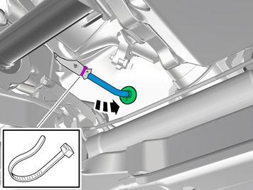
| | Applies to cars with already installed engine heater Cut off the tie strap holding the cable joint inside the subframe. Detach the cable from the clips in the subframe.
|
|  | | IMG-232583 |
|
| | Applies to cars with already installed engine heater Remove the locking sleeve over the cable splice and separate the cables.
|
|  | | IMG-232584 |
|
| | |
|  | | D3601932 |
|
| | Take a junction connector, joint cable for passenger compartment connector socket and three locking sleeves form the kit. Use low temperature grease, part no.1161427, to grease O-rings on: the connector to the front engine block heater socket both connectors on the junction connector the connector to the joint cable for the passenger compartment connector socket
Note!
Do not get any grease on the surfaces of the connector. |
|
|  | | IMG-232585 |
|
| | Take the locking sleeves from the kit. Connect the cables in accordance with the following: Cable (1) from the engine block heater. Joint cable (2) to the passenger compartment connector socket. Cable (3) from the front engine block heater socket. Press the cables firmly into the junction connector and press the locking sleeves in over the cable splices.
|
|  | | IMG-232586 |
|
| | |
|  | | IMG-232589 |
|
| | |
|  | | IMG-232587 |
|
| | |
|  | | IMG-232588 |
|
| | |
|  | | IMG-232590 |
|
| | |
|  | | IMG-360125 |
|
|  | | IMG-360126 |
|
| | |
|  | | IMG-232592 |
|
| | Get two double strip clamps from the kit and fasten them on the engine mount on the right side of the engine's top. Get the strip clamp and fit it loosely through the hole in the engine mount's front edge.
|
|  | | IMG-232594 |
|
| | Route the cable to the passenger compartment connector and to the first installed strip clamp in the subframe's right front corner. Tighten down the cable. Pull in excess cable in the passenger compartment.
Note!
Do not clamp the cable directly to brake pipes, fuel lines, AC pipes or pipes to the power steering. |
|
|  | | IMG-360137 |
|
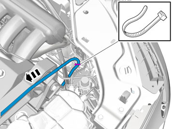
| | Continue to route the cable up on the outside of the right side member, up through the hole in the body on to the clamps at the location for the headlight. Route the cable under the servo pipes and up to the engine mount on the top of the engine. Secure the cable in the clamps behind the headlamp.
|
|  | | IMG-360016 |
|
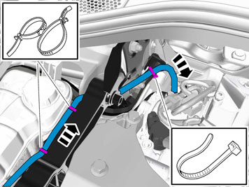
| | Route the cable up further along the engine mount on the top of the engine, and then down on the back of the engine, along the pipes to the power steering. The cable must be routed under the engine mount at its rear edge. Clamp the cable in at the previously positioned clamps.
|
|  | | IMG-232599 |
|
| | |
|  | | IMG-231839 |
|
| | |
|  | | IMG-298965 |
|
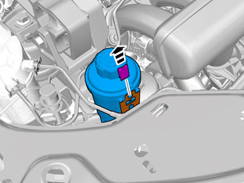
| | Grease in the rubber grommet using low temperature grease part no. 1161427 in order to make it easier to install the rubber grommet in the hole in the cowl wall.
Note!
Do not get any grease on the surfaces of the connector. |
Thread the rubber grommet on the cable.
|
|  | | IMG-360096 |
|
| | Insert the cable in the passenger compartment, adapt the cable length so that it runs out in the engine compartment and press the rubber grommet into place.
Take the grey strip clamp from the kit and tighten the heat shield to the cable at the rubber grommet.
|
|  | | IMG-289544 |
|
| | |
|  | | IMG-289546 |
|
| | |
|  | | IMG-298983 |
|
| | |
|  | | IMG-299003 |
|
| | |
|  | | IMG-299004 |
|
| | |
| | | IMG-360125 |
|
| | | IMG-360126 |
|
| | |
| | | IMG-232592 |
|
| | Get two double strip clamps from the kit and fasten them on the engine mount on the right side of the engine's top. Get the strip clamp and fit it loosely through the hole in the engine mount's front edge.
|
|  | | IMG-299023 |
|
| | |
| | | IMG-360137 |
|
| | Continue to route the cable up on the outside of the right side member, up through the hole in the body on to the clamps at the location for the headlight. Route the cable over the servo pipes and up to the engine mount on the top of the engine. Secure the cable in the clamps behind the headlamp.
|
| | | IMG-360016 |
|
| | Route the cable up further along the engine mount on the top of the engine, and then down on the back of the engine, along the pipes to the power steering. The cable must be routed under the engine mount at its rear edge. Clamp the cable in at the previously positioned clamps.
|
|  | | IMG-299043 |
|
| | |
| | | IMG-231839 |
|
| | |
|  | | IMG-299044 |
|
| | |
| | | IMG-360096 |
|
| | Insert the cable in the passenger compartment, adapt the cable length so that it runs out in the engine compartment and press the rubber grommet into place.
Take the grey strip clamp from the kit and tighten the heat shield to the cable at the rubber grommet.
|
|  | | IMG-231335 |
|
| | |
|  | | IMG-232602 |
|
| | |
|  | | IMG-232603 |
|
| | |
|  | | IMG-289547 |
|
| | |
|  | | IMG-289545 |
|
| | |
|  | | IMG-232604 |
|
| | |
|  | | IMG-217776 |
|
|  | | IMG-217777 |
|
| | A B Route the cable from the engine compartment through the hole in the carpet. Grease the O-ring with low temperature grease, part no. 1161427.
Note!
Ensure that no grease gets onto the connector surfaces. |
Connect the cable to the passenger compartment connector socket. Press a locking sleeve (from the kit) over the joint. Fold the carpet back into position and install the passenger compartment connector socket using both the screws.
|
|  | | IMG-234260 |
|
| | |