| | |
| | Read through all of the instructions before starting installation. Notifications and warning texts are for your safety and to minimise the risk of something breaking during installation. Ensure that all tools stated in the instructions are available before starting installation. Certain steps in the instructions are only presented in the form of images. Explanatory text is also given for more complicated steps. In the event of any problems with the instructions or the accessory, contact your local Volvo dealer.
|
| | |
|  | | IMG-400010 |
|
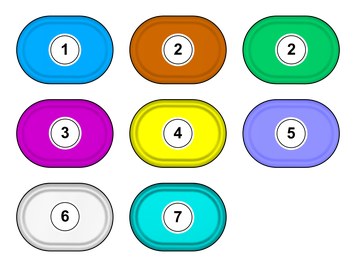
| | Note!
This colour chart displays (in colour print and electronic version) the importance of the different colours used in the images of the method steps. |
Used for focused component, the component with which you will do something. Used as extra colors when you need to show or differentiate additional parts. Used for attachments that are to be removed/installed. May be screws, clips, connectors, etc. Used when the component is not fully removed from the vehicle but only hung to the side. Used for standard tools and special tools. Used as background color for vehicle components. Used for accessory components.
|
| | |
|  | | IMG-498749 |
|
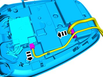
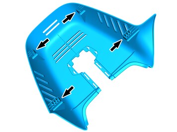
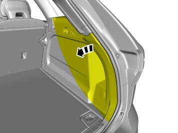
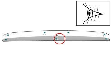
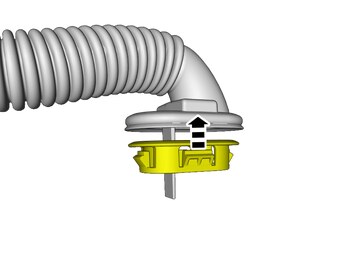
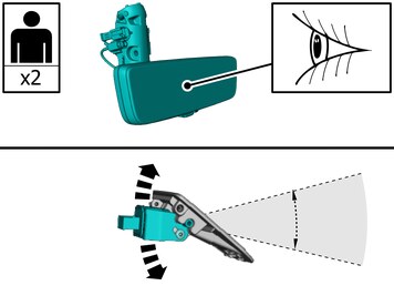
| | Note!
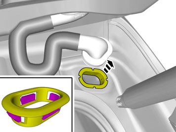
The graphic shows the back of the component before removal. |
|
|  | | IMG-491186 |
|
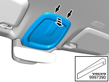
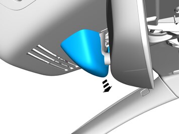
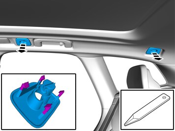
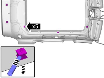
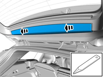
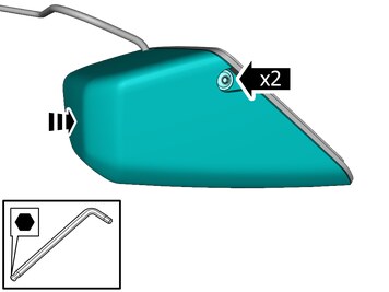
| | Caution!
Be careful, the frame of the component may break. |
Loosen the marked detail.
Use special tool: T9997390, Key
|
|  | | IMG-491070 |
|
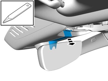
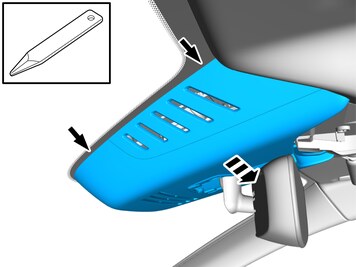
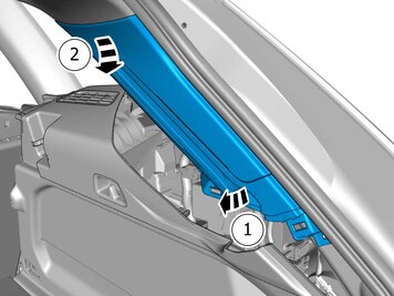
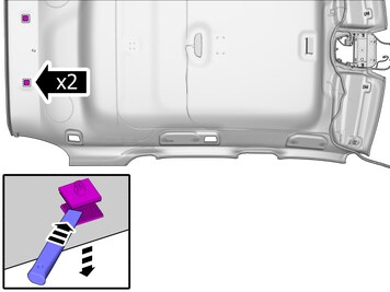
| | Pull the component in direction of the arrow. Depress the locking device. Repeat on the other side. Loosen the marked detail. |
|  | | IMG-491187 |
|
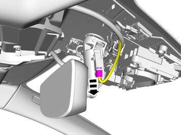
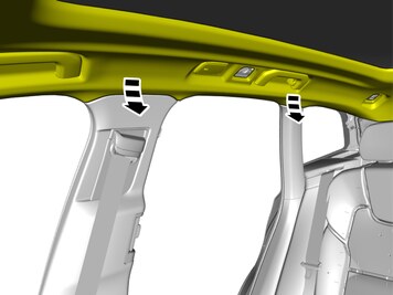
| | Disconnect the connectors. Remove the marked part. |
|  | | IMG-498971 |
|
| | |
|  | | IMG-498752 |
|
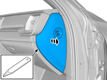
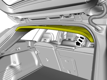
| | Remove the panel. Use: Interior trim remover
|
|  | | IMG-483016 |
|
| | |
|  | | IMG-483019 |
|
| | Note!
The graphic shows the back of the component before removal. |
|
|  | | IMG-483020 |
|
| | Release the catches. Repeat on the other side. Remove the panel. |
|  | | IMG-483021 |
|
| | Caution!
The number of connectors, cables and cable ties may vary depending on the vehicle specification. |
Disconnect the connector. |
|  | | IMG-483022 |
|
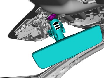
| | Caution!
Only turn at the base of the mirror. |
Remove the marked part. |
|  | | IMG-498756 |
|
| | Loosen the marked detail. |
|  | | IMG-498757 |
|
| | Loosen the marked detail. |
|  | | IMG-498758 |
|
| | |
|  | | IMG-498759 |
|
| | |
|  | | IMG-498760 |
|
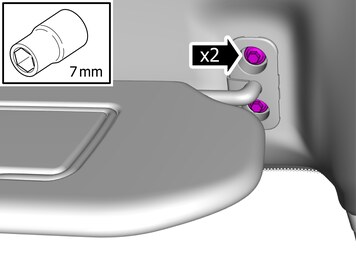
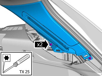
| | Remove the screws.
Tightening torque: M5
, 5 Nm
|
|  | | IMG-436053 |
|
| | Remove the panel. Disconnect the connector, if applicable. |
|  | | IMG-452102 |
|
| | |
|  | | IMG-491860 |
|
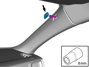
| | Remove the marked part. Remove the screw.
Tightening torque: Panel A-pillar
, 4.5 Nm
|
|  | | IMG-491865 |
|
| | |
|  | | IMG-499161 |
|
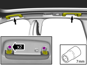
| | Remove the screws.
Tightening torque: Entry handle, to bracket
, 6 Nm
|
|  | | IMG-499165 |
|
| | |
|  | | IMG-499288 |
|
| | Loosen the component indicated. Do not remove it. |
|  | | IMG-499290 |
|
| | Remove the screws. Use: Magnetic bits holder socket
|
|  | | IMG-499291 |
|
| | |
| | Vehicles with glass roof panel |
|  | | IMG-499188 |
|
| |
Use special tool: T9997390, Key
Remove the part carefully |
| | Vehicles without glass roof panel |
|  | | IMG-499190 |
|
| |
Use special tool: T9997390, Key
Remove the part carefully |
| | |
|  | | IMG-499191 |
|
| | Caution!
Take extra care not to crease the headliner. |
Fold marked part aside. |
|  | | IMG-499197 |
|
| | |
|  | | IMG-499199 |
|
| | |
|  | | IMG-498130 |
|
| | The graphic shows the back of the component. |
|  | | IMG-499243 |
|
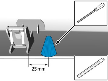
| | Measure Remove the marked part. Use: Round file
|
|  | | IMG-418825 |
|
| | Loosen the marked detail. To be repeated in the other end of the component. |
|  | | IMG-418831 |
|
| | Release the catches. Loosen the marked detail. To be repeated in the other end of the component. |
| | |
|  | | IMG-499245 |
|
| | Caution!
Make sure that the surface is clean and free of foreign material. |
Clean the marked area. Use: , Isopropanol
|
|  | | IMG-500795 |
|
| | |
|  | | IMG-498921 |
|
| | Remove the protective film. |
|  | | IMG-499259 |
|
| | Install components that come with the accessory kit. |
|  | | IMG-498933 |
|
| | Note!
Do not fully tighten the bolts. |
Install components that come with the accessory kit. Install the screws. |
|  | | IMG-491987 |
|
| | Use: 988734, Cable tie, 750 mm
|
|  | | IMG-498859 |
|
| | |
|  | | IMG-497736 |
|
| | |
|  | | IMG-500832 |
|
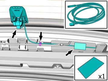
| | Connect the connector. Position/route the cable as illustrated. Apply tape. |
|  | | IMG-498492 |
|
| | Reinstall the removed part. To be repeated in the other end of the component. |
|  | | IMG-498511 |
|
| | Caution!
Make sure that the rubber grommet seals properly to the body. |
Reinstall the removed part. To be repeated in the other end of the component. |
|  | | IMG-499884 |
|
| | Caution!
The cable must not be placed too close to the outer edge. |
|
|  | | IMG-499317 |
|
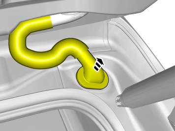
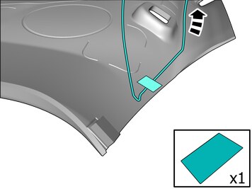
| | Position/route the cables as illustrated. Install the cable. Apply tape. |
| 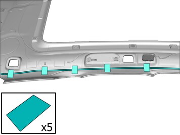 | | IMG-499314 |
|
| | Position/route the cable as illustrated. Install the cable. Apply tape. |
| 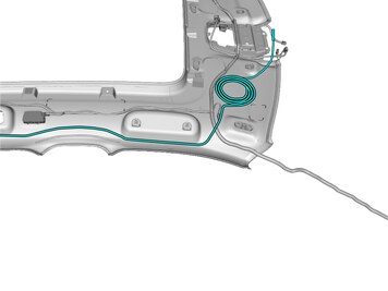 | | IMG-499242 |
|
| | Position/route the cable as illustrated. |
|  | | IMG-499158 |
|
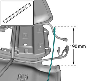
| | Measure Position/route the cable as illustrated. |
|  | | IMG-498830 |
|
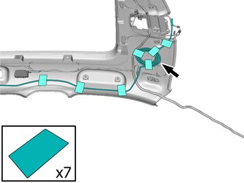
| | Position the cable harness excess as illustrated. Install the cable. Apply tape. |
|  | | IMG-498958 |
|
| | Assemble components that come with the accessory kit. |
|  | | IMG-499272 |
|
| | Caution!
Take extra care not to crease the headliner. |
Reinstall the removed part. |
|  | | IMG-498955 |
|
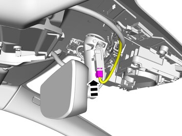
| | Caution!
Only turn at the base of the mirror. |
Install component that comes with the accessory kit. |
|  | | IMG-498956 |
|
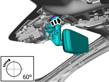
| | Rotate marked component according to image. |
|  | | IMG-498959 |
|
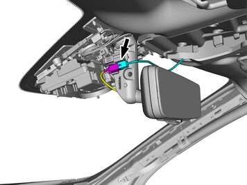
| | Connect the prerouted cable. |
|  | | IMG-498998 |
|
| | |
| | |
| | Reinstall the removed parts in reverse order. |
| | |
|  | | IMG-498995 |
|
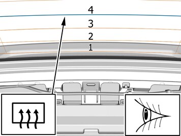
| | Note!
This step requires the aid of another technician. |
Adjust the camera angle outside. Make sure there is 20-30 meters of clear rear view. |
|  | | IMG-499003 |
|
| | |
|  | | IMG-499004 |
|
| | Install components that come with the accessory kit. Tighten the bolts. |


