| | |
|  | | IMG-316263 |
|
| | |
|  | | IMG-217771 |
|
| | |
|  | | IMG-231547 |
|
| | |
|  | | IMG-231549 |
|
| | |
|  | | IMG-231550 |
|
| | |
|  | | IMG-231551 |
|
| | |
|  | | IMG-231309 |
|
| | |
|  | | IMG-265069 |
|
| | |
|  | | IMG-265070 |
|
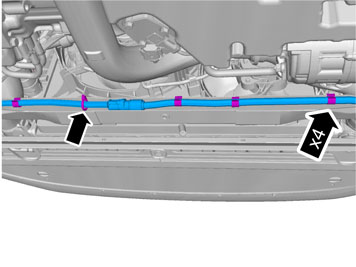
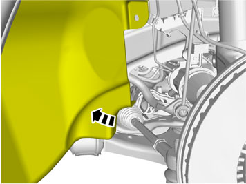
| | Remove the four screws from the front edge of the wheel arch liner on the left-hand side. Remove the bumper section on the left-hand side by pulling it forwards at the same time as bending the air baffle down.
|
|  | | IMG-265071 |
|
| | |
|  | | IMG-265072 |
|
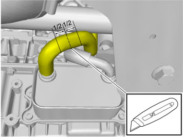
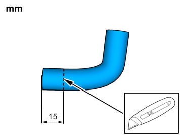
| | Accessory installation Note!
Cut carefully. It is easy to slip with the knife and move outside the markings. |
Note!
Ensure that the protective cover is turned the correct way (shown in next image). |
|
|  | | IMG-265073 |
|
| | Install the fog lamp connector and parking assistance, if applicable and reinstall the bumper section. Using a sharp knife, first make a thin cut along the edges of the inner section of the bumper. Then carefully cut out the inner section of the bumper flush with the prepared hole on the outer bumper section.
Note!
Cut carefully. It is easy to slip with the knife and move outside. |
Note!
Ensure that the protective cover is turned the correct way, see image. |
|
| | | IMG-231551 |
|
| | |
|  | | IMG-231564 |
|
| | Press the protective cover from the kit into place in the hole cut in the bumper cover. Take the cable for the front engine block heater socket with ground lead from the kit and thread them through the protective cover.
|
|  | | IMG-231566 |
|
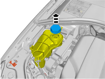
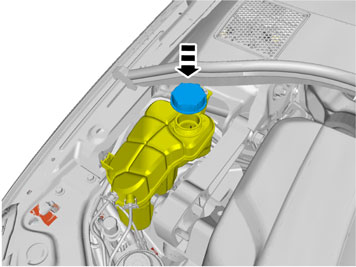
| | Install the attaching brace and nut from the kit. Plug the electrical connector into the front engine block heater socket. Use the connector as a counterhold when tightening. Tighten the front engine block heater socket to the bumper shell. Press the cable into the holder on the washer fluid reservoir.
|
|  | | IMG-231565 |
|
| | |
|  | | IMG-231567 |
|
| | |
|  | | IMG-231568 |
|
| | |
|  | | IMG-231571 |
|
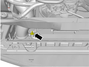
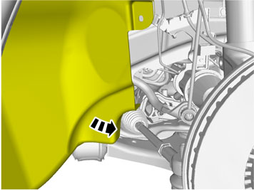
| | Drill a Ø 4mm (5/32 ") hole for the front intake grounding on the underside of the left front side member as illustrated. Deburr the hole edges, remove the drill swarf and apply rustproofing agent. Take a screw and toothed washer from the kit and tighten in the ground cable.
|
|  | | IMG-316303 |
|
| | |
|  | | IMG-316564 |
|
| | |
|  | | IMG-316566 |
|
| | |
|  | | IMG-316568 |
|
| | |
|  | | IMG-316571 |
|
| | |
|  | | IMG-316583 |
|
| | |
|  | | IMG-214121 |
|
| | Note!
The screws are self-tapping so it may be slow inserting them. Make sure that the screws are centred straight into the holes, so that the screw heads are flat against the bracket. |
|
|  | | IMG-214122 |
|
| | |
|  | | IMG-214125 |
|
| | |
|  | | IMG-377570 |
|
| | |
|  | | IMG-316743 |
|
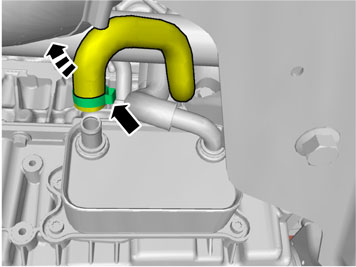
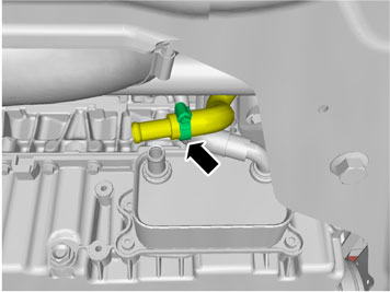
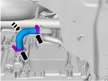
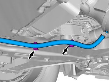
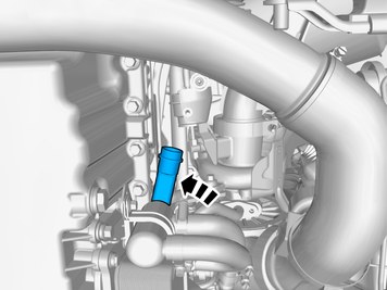
| | Install the hose between the earlier installed junction nipple and the upper connection in the engine heater. Tighten the clamps securely. Make sure that the hoses do not rub against the drive shaft or hose clamps.
|
|  | | IMG-316744 |
|
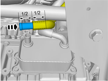
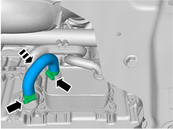
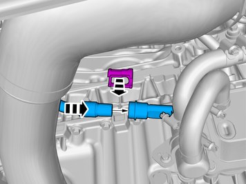
| | Get the last junction hose and the two remaining hose clamps from the kit. Connect the junction hose between the remaining connections in the engine heater and the oil cooler. Tighten the clamps securely.
|
|  | | IMG-317737 |
|
| | |
|  | | IMG-317740 |
|
| | |
|  | | D3601932 |
|
| | Note!
Do not get any grease on the surfaces of the connector. |
|
|  | | IMG-214136 |
|
| | Applies when only the engine block heater is installed |
|  | | IMG-317743 |
|
| | |
|  | | IMG-231576 |
|
| | Applies when fitting passenger compartment connector at the same time If the accessory passenger compartment connector is to be installed at the same time, install the junction connector now and lubricate the O-rings of the connector as described earlier. Connect: cable (1) from heater cable (2) to the passenger compartment connector socket cable (3) to the front inlet
|
|  | | IMG-317744 |
|
| | |
|  | | IMG-214133 |
|
| | |
|  | | IMG-214140 |
|
| | |
|  | | IMG-317748 |
|
| | |
|  | | IMG-214130 |
|
| | |
|  | | IMG-407095 |
|
| | |
|  | | IMG-214132 |
|
| | Note!
Do not clamp the cable directly to brake pipes, fuel lines, power steering pipes or AC pipes. |
|
|  | | IMG-214068 |
|
| | |
|  | | IMG-214131 |
|
| | |
|  | | IMG-214129 |
|
| | |
|  | | IMG-214128 |
|
| | |
|  | | IMG-214127 |
|
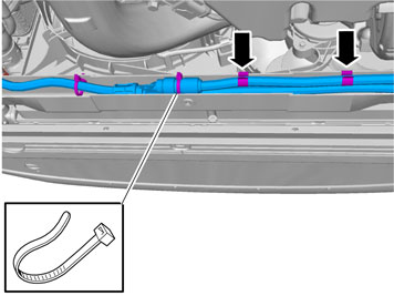
| | Reposition the radiation shield so that it covers the entire heater connector. Fasten the radiation shield to the heater's connector with the grey cable tie from the kit. Adjust the cable in the cable ties from the heater toward the front right corner of the subframe. Gather any excess cable length in the corner. Tighten all loose cable ties once the cable is routed in a manner that there is no risk of it being chafed or worn.
Note!
Make sure that the cable is routed so that it does not come into contact with the belt pulley, AC compressor belt or the drive shaft. |
|
|  | | IMG-406766 |
|
| | |
|  | | IMG-406765 |
|
| | |
|  | | IMG-317783 |
|
| | Note!
Make sure that the cable is kept away from the drive shaft. |
|
|  | | IMG-317784 |
|
| | |
|  | | IMG-231579 |
|
| | |
|  | | IMG-317785 |
|
| | |
|  | | IMG-231580 |
|
| | |
|  | | IMG-231581 |
|
| | |
|  | | IMG-231335 |
|
| | |
| | | IMG-265069 |
|
| | |
|  | | IMG-214062 |
|
| | |