| | |
|  | | A3000303 |
|
| | Preparations Note!
Wait at least one minute before unplugging the connectors or removing other electrical equipment. |
|
| | |
|  | | M8600738 |
|
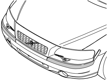
| | Removing the front bumper (applies to the V70) |
|  | | M8601212 |
|
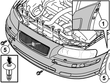
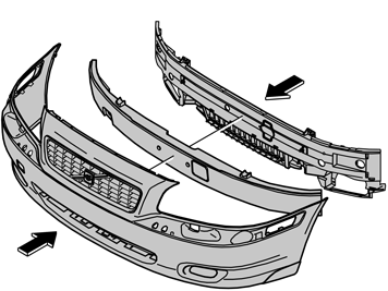
| | Unscrew the two screws (1) on both sides. Press down the centre pin in the six clips and remove them. Detach the two clips (5) on the underside of the bumper in the same way.
|
|  | | M8601214 |
|
| | Hint
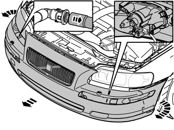
It is easier if two people perform this procedure. |
|
| | |
|  | | M8600694 |
|
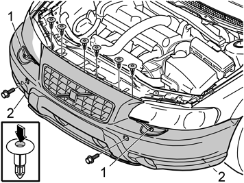
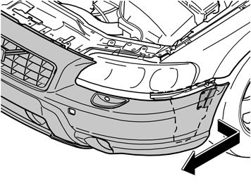
| | Removing the front bumper (applies to the XC70) Remove the cover and unscrew the two screws (1) on both sides. Press down the centre pin in the six clips and remove them. Detach the two clips (2) on the underside of the bumper in the same way.
|
|  | | M8600695 |
|
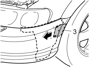
| | Unscrew the screw (3) but not completely. Press the screw head in so that it reaches the bottom and the shuttle releases. Repeat the operation on the other side.
|
|  | | M8600696 |
|
| | Hint
It is easier if two people perform this procedure. |
|
| | |
|  | | D8601321 |
|
| | |
|  | | D8600292 |
|
| | |
| | |
|  | | D8505048 |
|
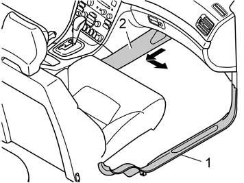
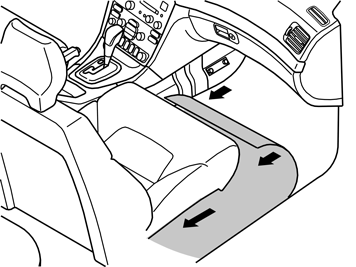
| | Preparations in the passenger compartment For right-hand drive cars: carry out the corresponding procedure on the left-hand side of the car. |
|  | | D8502325 |
|
| | |
|  | | D8505047 |
|
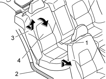
| | Detach the seat cushion (1) from the rear seat by pulling the cushion up at the front edge and then straight forward. Detach the right-hand sill (2) by the rear seat. Fold forward the right-hand section (4) of the rear seat Remove the seatbelt from the guide on the side bolster (3) Put your hand to the side of the lower section of the side bolster. Release the catches. At the same time lift the side bolster. Place the bolster to one side.
|
|  | | M8503188 |
|
| | |
|  | | M8503069 |
|
| | |
|  | | M8503008 |
|
| | |
|  | | D3703519 |
|
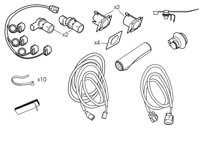
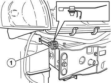
| | Installing the cable harness from the bumper Illustrations 15-20 show a left-hand drive car. For right-hand drive cars: carry out the corresponding procedure on the left-hand side of the car. Take the short cable harness from the kit. Detach the smaller connector from the cable. Fit the waterproofed connector (1) with plastic clamp / metal clip from the kit. Secure the plastic clamp around the connector and install the metal clip around the panel edge on the right-hand side of the car.
|
|  | | D2102942 |
|
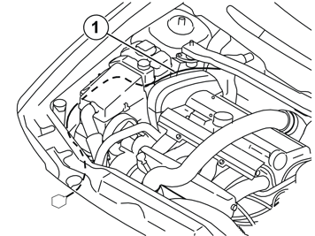
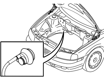
| | Pull the end of the cable with the loose pins into the engine compartment. Route the cable (1) as illustrated. Place it under the fuse holder and expansion tank so that it is concealed. Make sure that it is positioned so that it is not damaged by heat or wear. Clamp it in with tie straps from the kit.
|
|  | | D8200205 |
|
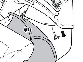
| | Cable routing to the passenger compartment If the car has a rubber grommet without any space for more cables Remove the existing rubber grommet and replace it with the rubber grommet from the kit.
If the car has a rubber grommet with space for more cables Cut off the tip of the unused rubber teat and route the cable into the passenger compartment. Thread on the rubber grommet from the kit. Lubricate the cable with normal soap so that the rubber grommet slides easily. Route the cable through the hole and press in the rubber grommet. Make sure that the cable's heating hose is in contact against the rubber grommet. Secure the heating hose with a tie strap.
|
|  | | D3703537 |
|
| | |
|  | | J3703487 |
|
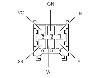
| | Blue (Blue, BL) Green (Green, GN) Violet (Violet, VO) Yellow (Yellow, Y) White (White, W) Black (Black, SB)
|
|  | | D8505053 |
|
|  | | M8503570 |
|
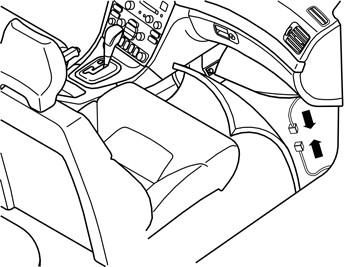
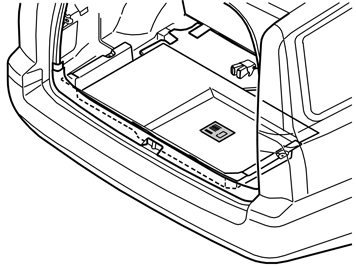
| | Illustration A Take the long cable from the kit. Attach the connector which has just been prepared. Route the cable over to the side of the car and on back under the sills along the existing cable harnesses backwards and into the cargo compartment.
Illustration B applies to left-hand drive cars |
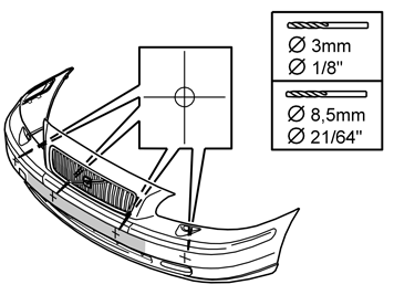
| | Hole drilling (applies to the V70) |
|  | | M8601360 |
|
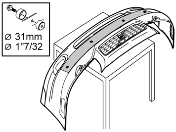
| | Hole drilling (applies to the V70) |
|  | | D8601358 |
|
| | |
|  | | M8601372 |
|
|  | | M8601375 |
|
| | Note!
The illustration shows the right-hand side. The corresponding work is also carried out on the left-hand side. |
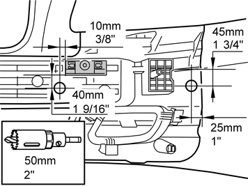
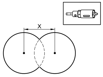
Drilling holes for the connectors Measure out and make hole markings for the sensors' connectors 30 mm to the right of the inner holes. Drill out the six holes in the inner plastic using a 50 mm diameter hole saw. The four inner holes are also drilled through the foam. Remove the foam. Cut out for the sensors' cables straight up in the foam from the holes which were opened up for the sensors' connectors, to the right of the inner holes.
|
| | Hole drilling (applies to the XC70) |
|  | | M8601236 |
|
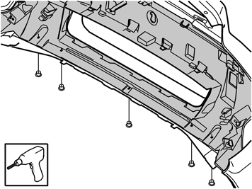
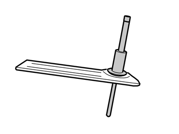
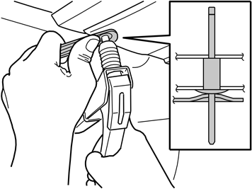
| | Hole drilling (applies to the XC70) Removing the skid plate Drill out the five blind rivets in the lower edge of the skid plate using a Ø6 mm diameter drill bit. Press in the ten catches holding the skid plate to the bumper cover. Remove the skid plate from the bumper cover.
|
|  | | IMG-214560 |
|
| | Drilling holes in the skid plate Note!
The illustration shows the right-hand side. The corresponding work is also carried out on the left-hand side. |
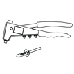
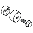
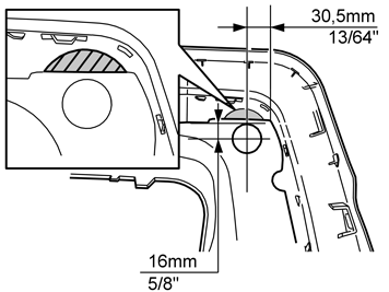
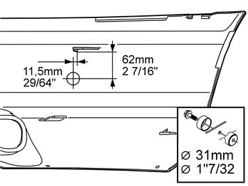
Measure out for the sensors' holes in the skid plate as illustrated. Pre-drill through the markings using a Ø3 mm diameter drill bit. Drill out the holes using a Ø8.5 mm diameter drill bit. Cut out in accordance with the marking so that the hole punching tool socket is level with the skid plate. Open the holes using a Ø31 mm diameter hole punching tool.
|
|  | | M8601362 |
|
|  | | IMG-214580 |
|
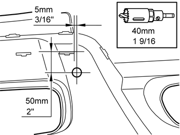
| | Drilling holes in the bumper Illustration A shows the outer holes being made Note!
The illustration shows the right-hand side. The corresponding work is also carried out on the left-hand side. |
Measure and mark out for the outer holes as illustrated. Drill Ø3 mm, Ø8.5 mm and punch open Ø31 mm the holes at the markings.
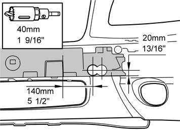
Illustration B shows the inner holes being made Note!
The illustration shows the right-hand side. The corresponding work is also carried out on the left-hand side. |
Measure and mark out for the inner holes as illustrated. Drill Ø3 mm, Ø8.5 mm and punch open Ø40 mm the holes at the markings.
|
|  | | M8601373 |
|
|  | | M8601375 |
|
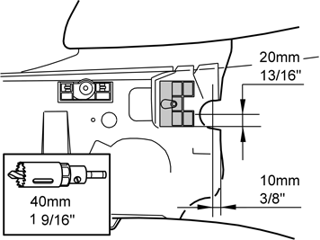
| | Drilling holes in the foam and rear section Illustration A shows measuring for the sensor holders in the foam Note!
The illustration shows the right-hand side. The corresponding work is also carried out on the left-hand side. |
Illustration B shows measuring for the sensor connector sockets |
|  | | M8601374 |
|
| | Drilling holes in the rear section Note!
The illustration shows the right-hand side. The corresponding work is also carried out on the left-hand side. |
Note!
No holes are required for the inner sensors. |
|
| | Installing the sensor holders |
|  | | D8601325 |
|
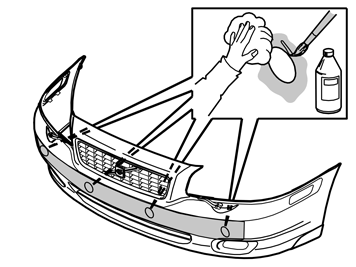
| | Installing the sensor holders Clean the inside of the bumper cover using a mild soap solution. Clean around the holes and their inner edges using a cleaning cloth. Allow to dry. Apply a thin layer of activator (P/N 8637076) on the cleaned surfaces. Allow to dry.
|
|  | | IMG-214381 |
|
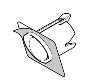
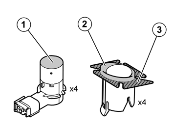
| | Clean the sensor surface (1) on the sensors, and the surfaces (2) and (3) on the sensor holders. Use a cleaning cloth. Allow to dry. Apply a thin layer of activator on the cleaned surfaces and allow to dry.
|
| | Illustration A Remove the protective backing tape from one side of the tape. Affix the tape to the front side of the sensor holders (see illustration B). Carry out the procedure above for the three other sensor holders. Check the marking on the rear side (A) of the sensor holders for the correct location.
Illustration B Note!
On the XC70 the inner sensor holders are located on the skid plate. |
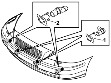
Holders marked with 2 (for sensors with straight connector) are located furthest out on the bumper. Check for correct location by fitting a sensor in each holder. The inner connectors must be turned to the right.
Illustration C Remove the protective film from the pieces of tape on the sensor holders. Install the sensor holders with the number marking pointing upwards. The top edge of the sensor holders must be horizontal to the bumper.
Note!
The tape adheres immediately. |
Note!
Incorrect positioning of the sensors may result in partial or complete malfunction. |
|
|  | | M8601277 |
|
|  | | M8601278 |
|
| | Installing the skid plate (applies to the XC70) Illustration A Illustration B |
| | Installing the sensors and cable harness |
|  | | M8601367 |
|
| | Installing the sensors and cable harness Note!
The illustration shows installation on a left-hand drive car. |
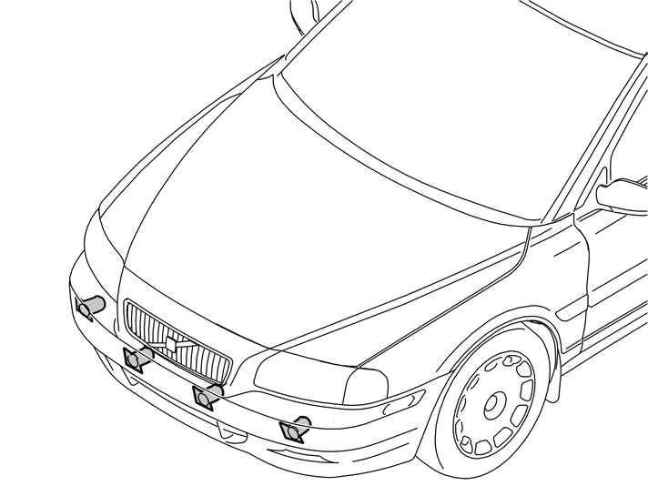
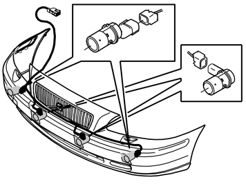
Take the sensors and their cable harness from the kit. Install the two sensors in the sensor holders so that they are securely fitted. The outer sensors are installed from below after the bumper has been reinstalled on the car. Attach the cable harness' connectors to the inner sensors. Make sure that the detached sensors in the outer position have sufficient cable to be installed after the bumper cover is fitted into place. The cable harness' detached connector should now appear on the side of the bumper.
Note!
When installing on right-hand drive cars the cable harness connector must come out on the left-hand side of the bumper. |
Note!
A click should be heard when connecting. The noise confirms that the catch has locked. |
|
|  | | D8601350 |
|
| | |
|  | | D8601330 |
|
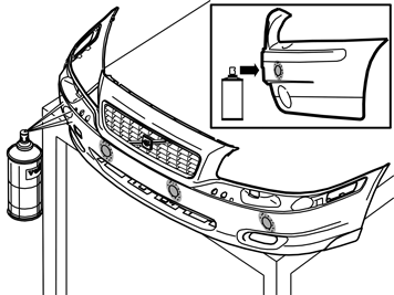
| | Note!
Take care to ensure that the activator has dried, at least ten minutes, before painting. |
Applies to the V70 Paint the sensors and holders using the same colour code paint as the car. Use paint recommended by Volvo. Apply a maximum of two coats. When the paint has dried, remove the protective backing paper.
Applies to the XC70 The inner sensors are painted with paint code: 426 silver. The outer sensors are only painted with clear coat. When the paint has dried, remove the protective backing paper.
Caution!
Too many layers of paint may result in partial or complete malfunction. All sensors must be painted to achieve optimum function. |
|
|  | | M8601341 |
|
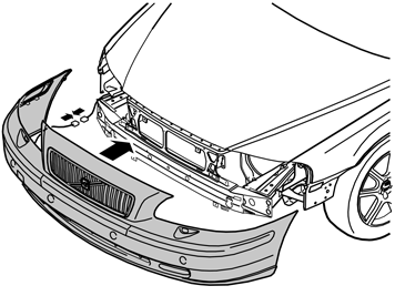
| | Hold the bumper up against the car and connect the connector for the sensors to the connector clamped to the car. Reinstall the bumper by repeating the instructions in steps 2-5 in reverse order. Install the two outer sensors in the sensor holders and connect them to the routed cable harness (see illustration 34).
|
|  | | D3905107 |
|
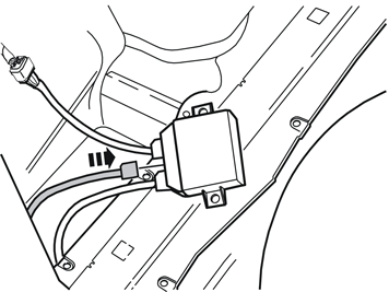
| | Note!
Make sure that the connector clicks into place and is properly secured. |
|
| | |
| | |
| | |
| | |

