| | |
| | Read through all of the instructions before starting installation. Notifications and warning texts are for your safety and to minimise the risk of something breaking during installation. Ensure that all tools stated in the instructions are available before starting installation. Certain steps in the instructions are only presented in the form of images. Explanatory text is also given for more complicated steps. In the event of any problems with the instructions or the accessory, contact your local Volvo dealer.
|
| | |
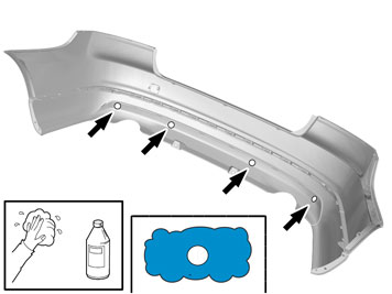
| | Note!
Make sure that the customer is advised not to wash the vehicle within the next 72 hours. |
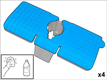
Note!
Make sure that the mating faces are at a minimum temperature of 20°C. |
When installing, the car must retain a temperature of 20 degrees C. After installation, the car must not be driven for 2 hours |
|  | | IMG-377194 |
|
| | |
|  | | IMG-352653 |
|
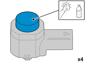
| | Clean the surface. Use: 1161721, Isopropanol
Allow to dry. |
|  | | IMG-352654 |
|
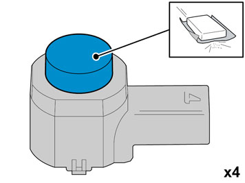
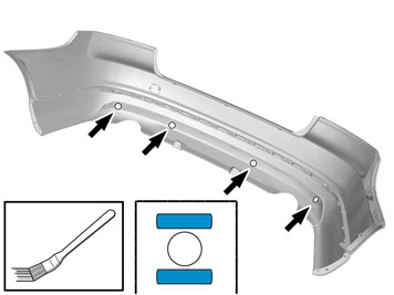
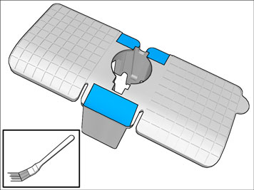
| | Matt the surface gently. Use: , Sand paper P1000
|
| | | IMG-352653 |
|
| | Clean the surface. Use: 1161721, Isopropanol
Allow to dry. |
|  | | IMG-352655 |
|
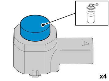
| | Caution!
Protect connector surfaces against paint spray. |
Note!
Paint the sensors the same colour code as the vehicle. |
Use: , Volvo Original Touch-up paint
Use base coat only. Use: 31335447, Varnish 2-component
Also see the instructions on the container. |
|  | | IMG-352658 |
|
| | Caution!
First the paint must dry after painting. |
|
| | |
|  | | IMG-332193 |
|
| | Set the ignition key to position 0. |
|  | | IMG-377098 |
|
| | |
|  | | IMG-372212 |
|
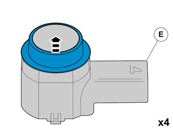
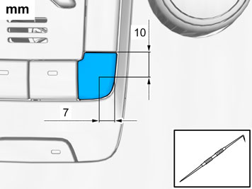
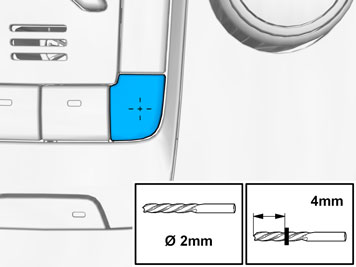
| | Measure and mark as illustrated. |
|  | | IMG-372210 |
|
| | |
|  | | IMG-372209 |
|
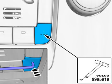
| |
Use special tool: T9995919, PULLER (SEAL-PINION,CAM-CRANKSHAFT)B200-6304
|
|  | | IMG-372207 |
|
| | |
| | |
|  | | IMG-372208 |
|
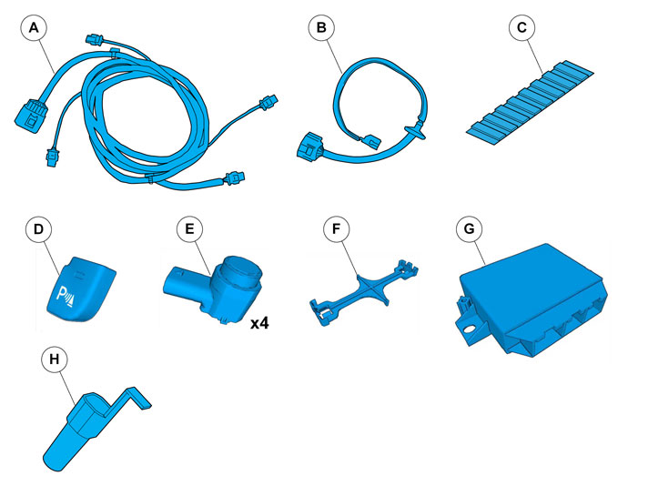
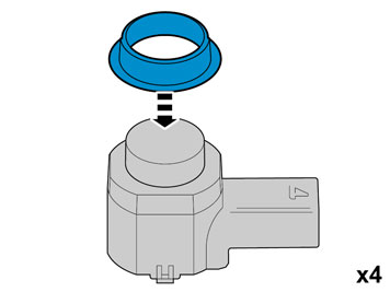
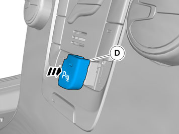
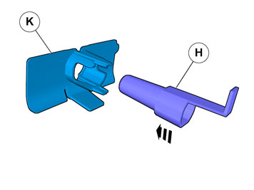
| | Install component that comes with the accessory kit. |
| | |
|  | | IMG-247266 |
|
| | |
|  | | IMG-211568 |
|
| | |
|  | | IMG-247267 |
|
| | |
|  | | IMG-377070 |
|
| | Repeat the steps when removing on opposite side. |
|  | | IMG-247268 |
|
| | |
| | |
|  | | IMG-377128 |
|
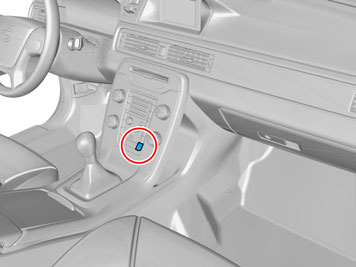
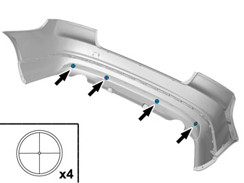
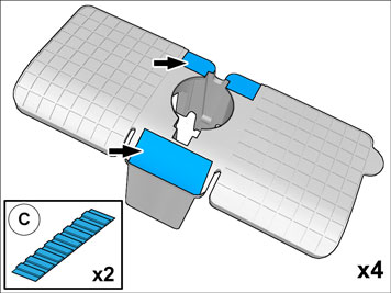
| | Locate the markings for the positions. |
|  | | IMG-377129 |
|
| | |
|  | | IMG-377127 |
|
| | |
|  | | IMG-377126 |
|
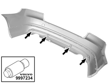
| | Caution!
Sharp end of tool must be on outside of cover. |
Use special tool: T9997234, Hole stamp
|
|  | | IMG-377125 |
|
| | Clean the surfaces. Use: 1161721, Isopropanol
Allow to dry. |
|  | | IMG-377130 |
|
| | Clean the surface. Use: 1161721, Isopropanol
Allow to dry. |
|  | | IMG-377124 |
|
| | Apply a thin and even layer. Use: 8637076, Activator
Allow to dry for at least 10 minutes. |
|  | | IMG-377131 |
|
| | Apply a thin and even layer. Use: 8637076, Activator
Allow to dry for at least 10 minutes. |
| | |
|  | | IMG-226907 |
|
| | |
|  | | IMG-226722 |
|
| | |
|  | | IMG-255684 |
|
| | |
|  | | IMG-377132 |
|
| | Remove the nuts. Remove the clips. Disconnect the connector. |
|  | | IMG-274367 |
|
| | |
| | |
|  | | IMG-247272 |
|
| | |
|  | | IMG-247273 |
|
| | |
|  | | IMG-247274 |
|
| | The part is not to be reused. |
|  | | IMG-377135 |
|
| | |
|  | | IMG-247276 |
|
| | Caution!
Make sure that the rubber grommet seals properly to the body. |
|
|  | | IMG-377133 |
|
| | Reinstall the removed part. |
|  | | IMG-247277 |
|
| | |
|  | | IMG-247278 |
|
| | |
|  | | IMG-247279 |
|
| | Locate the existing connector in the vehicle's cable harness. Connect the connector. |
|  | | IMG-377195 |
|
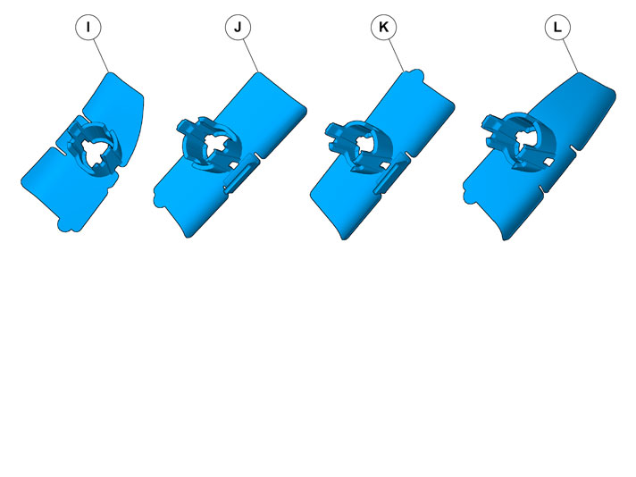
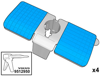
| | Note!
Prepare and install one holder at a time. |
|
|  | | IMG-377196 |
|
| | Note!
Ensure that the tape is fixed to the surface. |
Remove the protective film. |
|  | | IMG-377137 |
|
| | Warning!
Make sure to provide adequate ventilation. |
Warning!
Wear protective gloves. |
Apply a thin and even layer.
Use special tool: T9512950, Glue gun (kit)
Use: 1161730, Mixing pipe
Use: 9511027, Glue
|
|  | | IMG-377177 |
|
| | |
|  | | IMG-377178 |
|
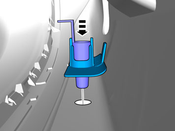
| | Note!
Apply pressure only where the tape is located. |
|
|  | | IMG-377179 |
|
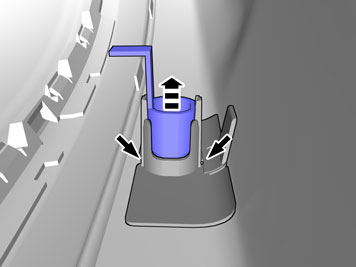
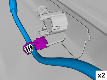
| | Note!
Hold the part securely at the marker arrows when removing the tool. |
|
|  | | IMG-377142 |
|
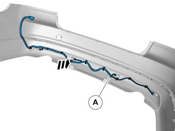
| | Put the wiring in the Bumper cover without installing the wiring. |
|  | | IMG-373743 |
|
| | |
|  | | IMG-377181 |
|
| | |
|  | | IMG-377184 |
|
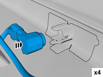
| | Caution!
Hold the newly bonded sensor holder in position whilst pressing the clip into position. |
|
| 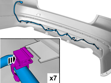 | | IMG-377185 |
|
| | |
| | |
|  | | IMG-247290 |
|
| | Place the Bumper Cover in position for installation. Connect the connector. |
| | | IMG-377070 |
|
| | Reinstall the removed parts in reverse order. |
|  | | IMG-242268 |
|
| | Download software (application) for the accessory's function according to the service information in VIDA. Order and download software according to: 30765571
|