| | |
| | Read through all of the instructions before starting installation. Notifications and warning texts are for your safety and to minimise the risk of something breaking during installation. Ensure that all tools stated in the instructions are available before starting installation. Certain steps in the instructions are only presented in the form of images. Explanatory text is also given for more complicated steps. In the event of any problems with the instructions or the accessory, contact your local Volvo dealer.
|
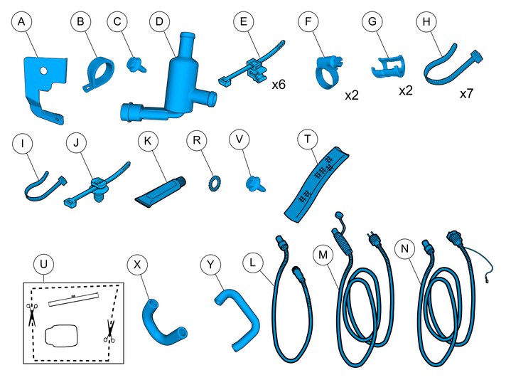
| | There may be parts in the accessories kit that are not needed for this installation. |
| | |
|  | | IMG-363036 |
|
| | Note!
This colour chart displays (in colour print and electronic version) the importance of the different colours used in the images of the method steps. |
Used for focused component, the component with which you will do something. Used as extra colors when you need to show or differentiate additional parts. Used for attachments that are to be removed/installed. May be screws, clips, connectors, etc. Used when the component is not fully removed from the vehicle but only hung to the side. Used for standard tools and special tools. Used as background color for vehicle components.
|
| | |
|  | | IMG-332193 |
|
| | Set the ignition key to position 0. |
|  | | IMG-362805 |
|
| | |
|  | | IMG-362807 |
|
| | |
|  | | IMG-368369 |
|
| | |
|  | | IMG-368376 |
|
| | |
|  | | IMG-362811 |
|
| | |
|  | | IMG-371233 |
|
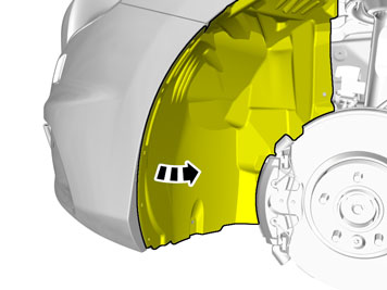
| | Fold the wing liner aside. |
| | |
|  | | IMG-372264 |
|
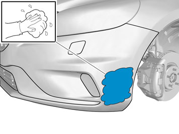
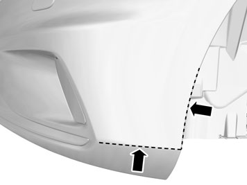
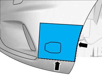
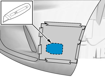
| | Clean the Bumper Cover surface. |
|  | | IMG-372299 |
|
| | Take the template from the kit and cut it out following the dotted line. |
|  | | IMG-372272 |
|
| | |
|  | | IMG-372273 |
|
| | |
|  | | IMG-372275 |
|
| | |
|  | | IMG-372276 |
|
| | Caution!
Cut carefully to avoid unintentional damage or personal injury. |
|
|  | | IMG-383193 |
|
| | |
|  | | IMG-372277 |
|
| | |
|  | | IMG-383195 |
|
| | |
|  | | IMG-363401 |
|
| | |
| | |
|  | | IMG-358506 |
|
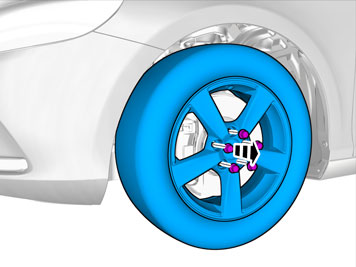
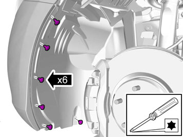
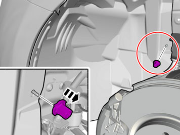
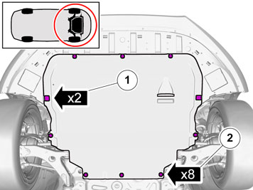
| | Raise the car. Remove the clips. Remove the screws.
|
|  | | IMG-358531 |
|
| | |
|  | | IMG-386654 |
|
| | |
|  | | IMG-386007 |
|
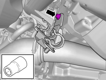
| | Remove the screw. The part is to be reused. |
|  | | IMG-385808 |
|
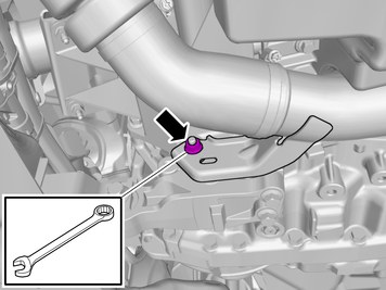
| | Remove the nut. The part is to be reused. |
|  | | IMG-386656 |
|
| | |
|  | | IMG-386658 |
|
| | |
|  | | IMG-386556 |
|
| | |
|  | | IMG-386494 |
|
| | |
|  | | IMG-386496 |
|
| | |
|  | | IMG-386498 |
|
| | |
|  | | IMG-371659 |
|
| | |
|  | | IMG-371658 |
|
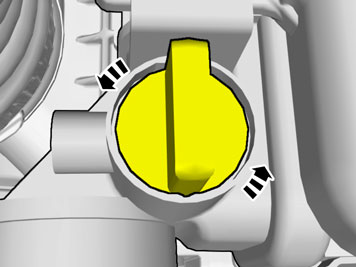
| | Note!
Close the drain cock after the coolant has drained. |
Place a container under the car. Drain the coolant. |
| | |
|  | | IMG-383219 |
|
| | |
|  | | IMG-383289 |
|
| | |
|  | | IMG-383291 |
|
| | |
|  | | IMG-383221 |
|
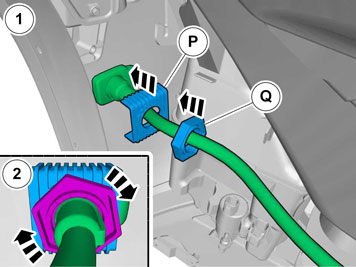
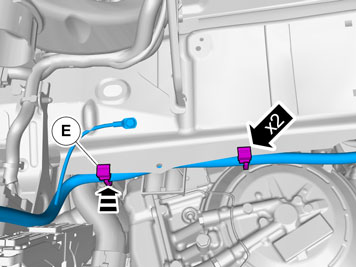
| | Install the clip(s). Tighten the cable ties. |
|  | | IMG-383226 |
|
| | |
|  | | IMG-387205 |
|
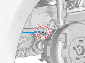
| | Install the clip(s). Tighten the cable ties. |
|  | | IMG-383229 |
|
| | |
|  | | IMG-383230 |
|
| | |
|  | | IMG-387258 |
|
| | |
|  | | IMG-387266 |
|
| | Connect the connector. Install the catch. |
|  | | IMG-384539 |
|
| | |
|  | | IMG-386653 |
|
| | |
|  | | IMG-384541 |
|
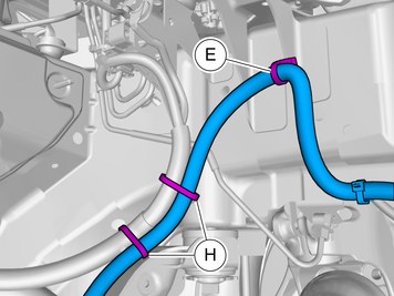
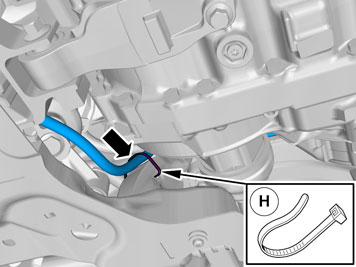
| | Install the clip(s). Tighten the cable tie. |
|  | | IMG-384542 |
|
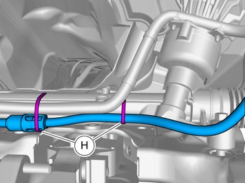
| | Install the clip(s). Tighten the cable tie. |
|  | | IMG-386360 |
|
| | |
|  | | IMG-386350 |
|
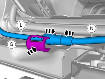
| | Clamp using the grey cable tie. |
|  | | IMG-384558 |
|
| | Install the clip(s). Clamp using the grey cable tie. |
| | |
| | | IMG-386556 |
|
| | |
|  | | IMG-383344 |
|
| | |
|  | | IMG-383340 |
|
| | |
|  | | IMG-383342 |
|
| | |
|  | | IMG-386503 |
|
| | The part is not to be reused. |
| | |
| | | IMG-386556 |
|
| | |
|  | | IMG-387744 |
|
| | Install component that comes with the accessory kit. |
|  | | IMG-387745 |
|
| | Install the nut.
Tightening torque: M8
, 24 Nm
|
|  | | IMG-387746 |
|
| | |
|  | | IMG-387751 |
|
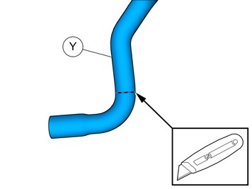
| | Caution!
Cut carefully to avoid unintentional damage or personal injury. |
|
|  | | IMG-386509 |
|
| | Install component that comes with the accessory kit. |
|  | | IMG-387752 |
|
| | |
|  | | IMG-387753 |
|
| | |
|  | | IMG-383266 |
|
| | |
|  | | IMG-387838 |
|
| | |
|  | | IMG-383261 |
|
| | Install the screw.
Tightening torque: M6
, 10 Nm
|
|  | | IMG-386255 |
|
| | |
|  | | IMG-387305 |
|
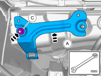
| | Install the nut.
Tightening torque: M8
, 24 Nm
|
| | | IMG-386556 |
|
| | |
|  | | IMG-386539 |
|
| | |
|  | | IMG-387768 |
|
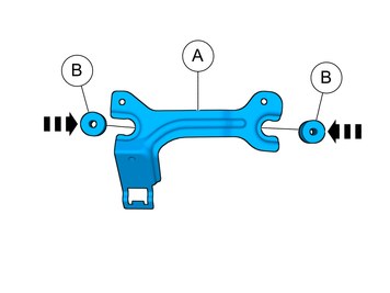
| | Install component that comes with the accessory kit. |
|  | | IMG-387779 |
|
| | Install the clip(s). Tighten the cable tie. |
|  | | IMG-387818 |
|
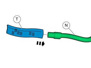
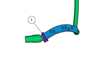
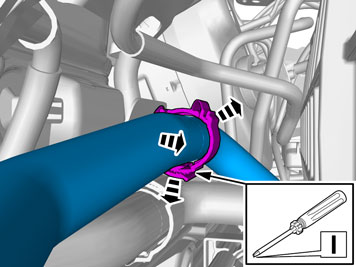
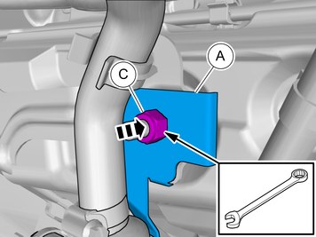
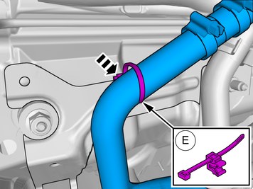
| | Install component that comes with the accessory kit. Tighten the hose clamp. |
|  | | IMG-362914 |
|
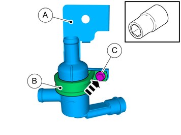
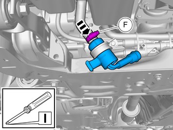
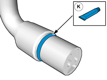
| | Caution!
No grease on contact surfaces. |
Lubricate the O-ring. Use: 1161427, Low temperature grease
|
|  | | IMG-386103 |
|
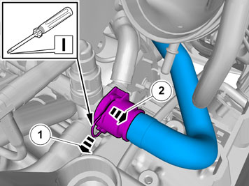
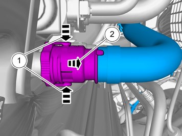
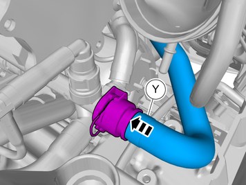
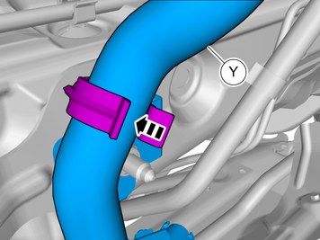
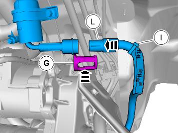
| | Connect the connector. Install the catch. |
| | |
|  | | IMG-363206 |
|
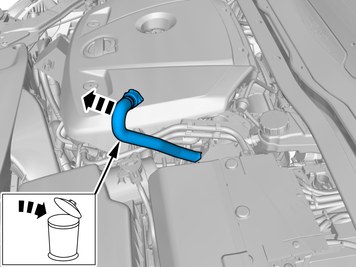
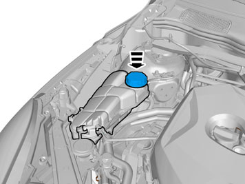
| | Fill with coolant and run the engine to operating temperature. Vent the cooling system and check for leakage. Post-fill the cooling system if necessary. |
| | Reinstall the removed parts in reverse order. |
|  | | IMG-370207 |
|
| | |
|  | | IMG-370203 |
|
| | |