2008 L.H.D

Installation Instruction

Installation instructions, accessories
Volvo Car Corporation Gothenburg, Sweden
C70 2008
C70 (06-) 2008

Instruction NoVersionPart. No.Click to download PDF-version of this Installation Instruction
307720431.230752453
AEM


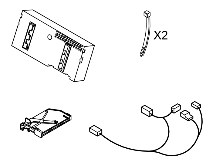
Equipment
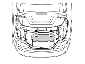
A0000162
A0000161

IMG-223821

IMG-213320


INTRODUCTION

  • Read through all of the instructions before starting installation.

  • Notifications and warning texts are for your safety and to minimise the risk of something breaking during installation.

  • Ensure that all tools stated in the instructions are available before starting installation.

  • Certain steps in the instructions are only presented in the form of images. Explanatory text is also given for more complicated steps.

  • In the event of any problems with the instructions or the accessory, contact your local Volvo dealer.

1
IMG-221940
 

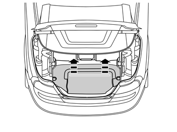
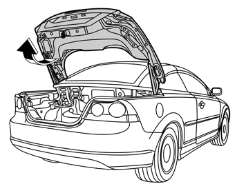
  • Open the boot lid/tailgate.

2
IMG-221661
 

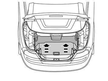
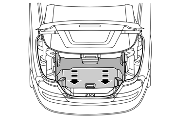
  • Lift up the cargo compartment divider.

3
IMG-242961
 

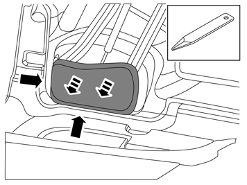
  • Remove the covers on each side of the divider.

4
IMG-242962
 

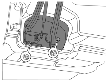
  • Unscrew the two nuts 4 revolutions (on each side of the divider).

5
IMG-242963
 

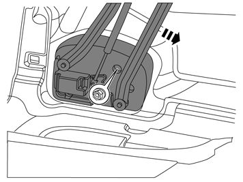
  • Lower the divider slightly.

  • Unscrew the third nut on each side of the divider four turns.

6
IMG-226480
 

  • Lower the divider completely.

7
IMG-242964
 

  • Detach the wire frame from the clip.

8
IMG-226483
 

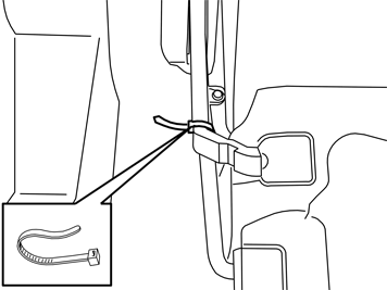
  • Use a cable tie or the like to lock the divider's two arms on the right and left side.

9
IMG-221942
 

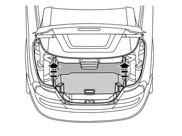
  • Remove the partition by taking hold of the arms and lifting upward.

10
IMG-221960
 

    Remove:

  • the cover of the toolbox.

  • the spare wheel, if in place.

11
IMG-221961
 

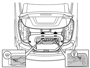
  • Take the tools out of the toolbox.

    Remove:

  • the clip.

  • the screw.

  • the toolbox.

12
IMG-221962
 

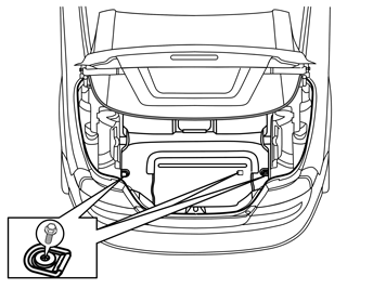
  • Remove the three screws and the lashing eyes from the floor.

13
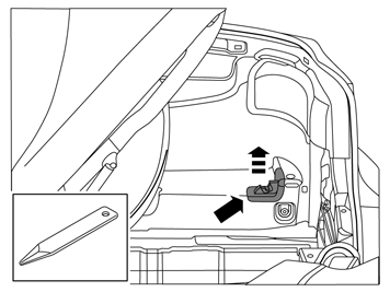
IMG-242965
 

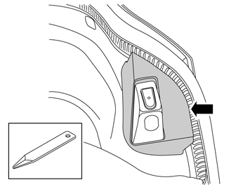
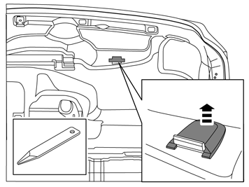
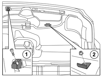
  • Remove the cover from the trunk lid stop. Use a weatherstrip tool to pry between the cover and the stop to release the catches.

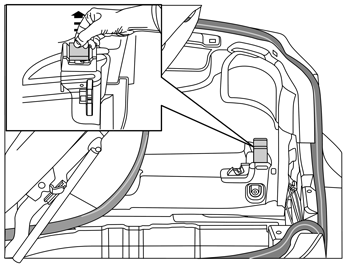
14
IMG-242966
 

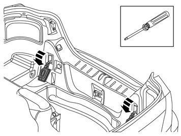
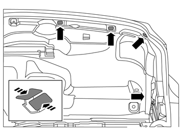
  • Remove the two light bulbs by pressing in the two catches at the top with a screwdriver.

15
IMG-242967
 

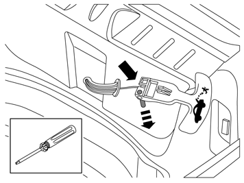
    For cars with emergency release handle in cargo compartment

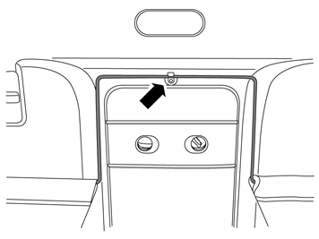
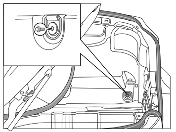
  • Remove the emergency release handle by pressing out the pin at the eye and unhooking the cable.

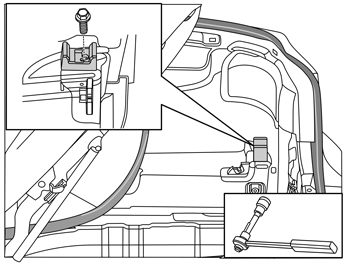
16
IMG-221966
 

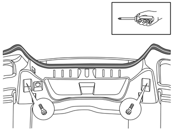
  • Remove the two screws in the sill moulding.

17
IMG-221967
 

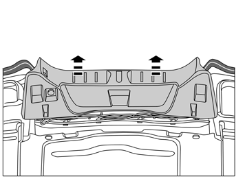
  • Remove the sill moulding by pulling it upward until the clips release. Move the sill moulding aside.

18
IMG-221968
 

  • Remove the cargo compartment carpeting.

19
IMG-221969
 

  • Remove the rubber stop on the roof's stop brace.

20
IMG-221972
 

  • Mark out the roof's stop brace in relation to the screw.

  • Remove the screw and the roof's stop brace.

21
IMG-242968
 

  • Remove the load divider lock by using a weatherstrip tool to pry between the carpet and lock.

22
IMG-221974
 

  • Remove the screw and the lashing eye on the right side.

23
IMG-242969
 

  • Remove the stop brace cover.

24
IMG-242970
 

  • Mark out the stop braces for the roof in relation to the screws and nuts on the right side.

  • Remove the screw, nut and the roof's stop braces.

25
IMG-221976
 

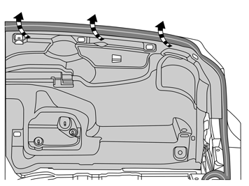
  • Undo the four clips on the side panel.

26
IMG-221978
 

  • Remove the side panel by unhooking it from the stop lug at the front edge and the pulling outward and upward so that it releases from the sealing strip.

27
IMG-223847
 

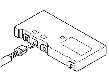
  • Plug the 4-pin black connector from the adapter wiring into the control module.

28
IMG-223841
 

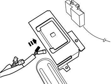
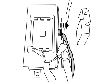
  • Thread the adapter wiring through the control module bracket.

29
IMG-223845
 

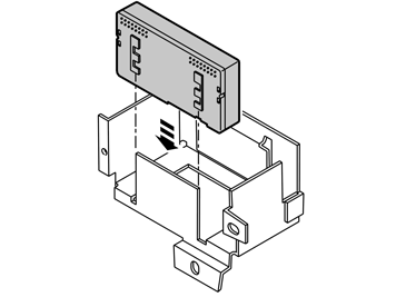
  • Install the control module by fitting it on the bracket rail.


    Note!

    The figure depicts a removed bracket.


30
IMG-244560
 

    Applies to cars with parking assistance

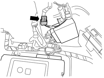
  • Locate the 4-pin green connector that is taped onto the parking assistance cable harness. Connect this to the adapter wiring.

  • Secure the loose connector with a cable tie.

31
IMG-223843
 

    For cars with trailer module (TRM)

  • Take the green connector from the control module and connect it to the adapter wiring.

  • Plug the adapter wiring connector into the control module.

  • Secure the loose connector with a cable tie.

32
IMG-223844
 

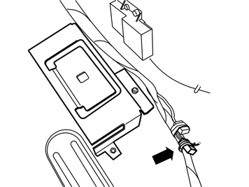
  • Locate the 4-pin green connector that is taped onto the car's standard cable harness. Connect this to the adapter wiring.

  • Secure the loose connector with a cable tie.

33
IMG-223842
 

  • Route the wiring along the car's cable harness all the way up to the sill moulding.

34
IMG-223846
 

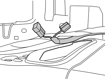
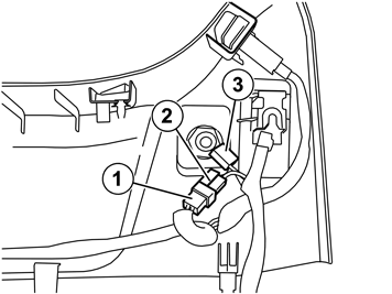
  • Remove the connector (1) on the sill moulding's 12 volt socket and connect it to the cable wiring (2). Plug connector (3) into the 12 volt socket.

  • Secure the loose connector with a cable tie.

35
 

    Reinstall:

  • the side panel.

  • stops and attaching braces.

  • the cargo compartment carpeting.

  • the sill panel with lighting.

  • any emergency release.

  • the stop for the boot lid/tailgate.

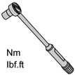
  • the lashing eyes; tighten the screws to 24 Nm (17 lbf.ft.).

  • the toolbox.

  • the partition; remove the cable ties.

  • Download the software for the accessory's function following the service information in VIDA.