| | |
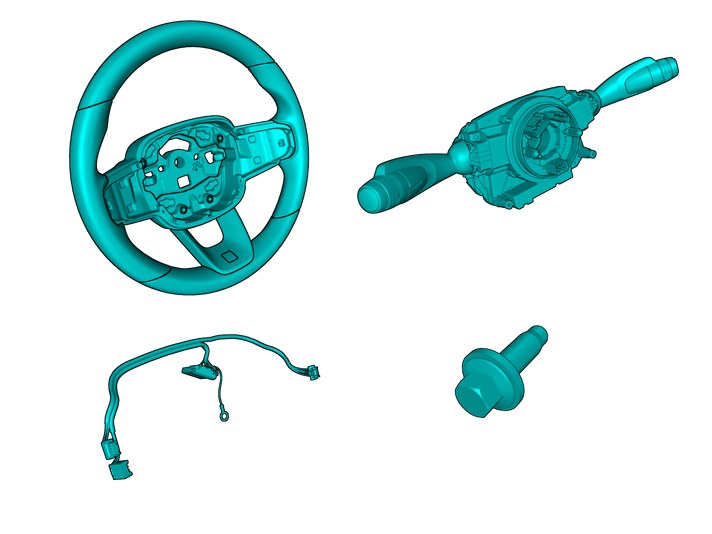
| | Read through all of the instructions before starting installation. Notifications and warning texts are for your safety and to minimise the risk of something breaking during installation. Ensure that all tools stated in the instructions are available before starting installation. Certain steps in the instructions are only presented in the form of images. Explanatory text is also given for more complicated steps. In the event of any problems with the instructions or the accessory, contact your local Volvo dealer.
|
| | |
|  | | IMG-400010 |
|
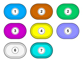
| | Note!
This colour chart displays (in colour print and electronic version) the importance of the different colours used in the images of the method steps. |
Used for focused component, the component with which you will do something. Used as extra colors when you need to show or differentiate additional parts. Used for attachments that are to be removed/installed. May be screws, clips, connectors, etc. Used when the component is not fully removed from the vehicle but only hung to the side. Used for standard tools and special tools. Used as background color for vehicle components. Used for accessory components.
|
| | |
|  | | IMG-462098 |
|
| | |
|  | | IMG-462002 |
|
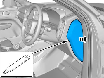
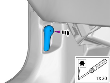
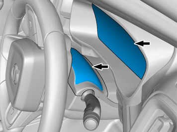
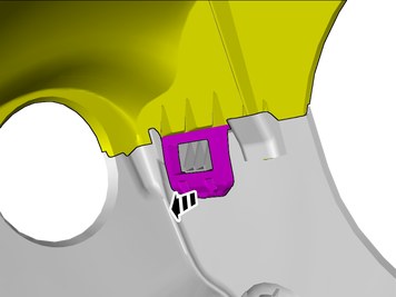
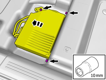
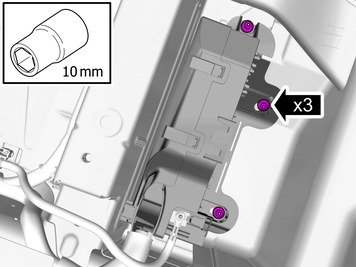
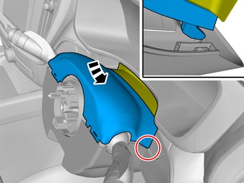
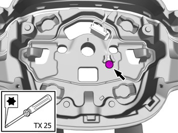
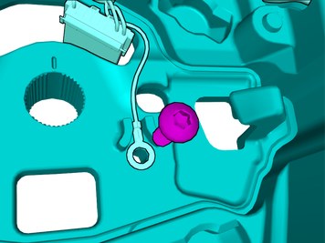
| | Caution!
Left side! This step applies also to right-hand drive vehicles! |
Remove the screw. Remove the marked part. |
|  | | IMG-462099 |
|
| | |
|  | | IMG-462100 |
|
| | |
|  | | IMG-462101 |
|
| | |
|  | | IMG-443405 |
|
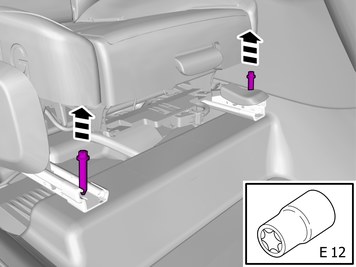
| |
Tightening torque: Front seat to body
, 40 Nm
|
|  | | IMG-462102 |
|
| | |
|  | | IMG-443407 |
|
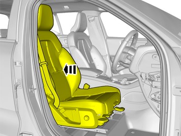
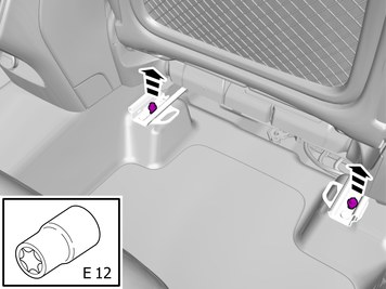
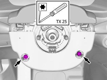
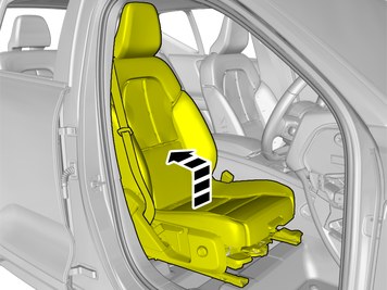
| | Remove the screws.
Tightening torque: Front seat to body
, 40 Nm
|
|  | | IMG-400000 |
|
| | Repeat the steps when removing on opposite side. |
| | Disconnecting the battery |
|  | | IMG-462297 |
|
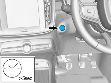
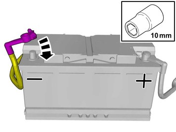
| | Note!
Make sure that the steering column lock is not engaged. |
Turn on the ignition. |
|  | | IMG-400002 |
|
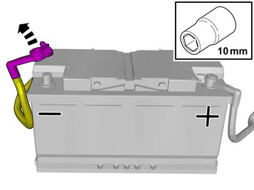
| | Remove the battery's negative cable. |
| | |
|  | | IMG-462103 |
|
| | |
|  | | IMG-462105 |
|
| | |
|  | | IMG-449570 |
|
| | |
|  | | IMG-462295 |
|
| | Caution!
Make sure to protect adjacent surfaces or components. |
|
|  | | IMG-462110 |
|
| | |
|  | | IMG-449577 |
|
| | |
|  | | IMG-462104 |
|
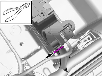
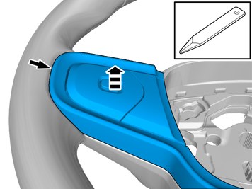
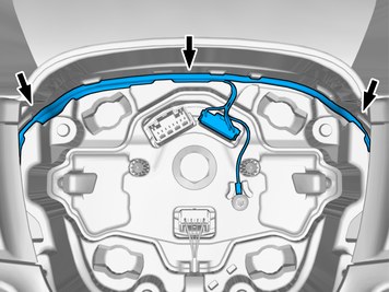
| | Release the catch. Loosen the marked detail.
|
|  | | IMG-462115 |
|
| | |
|  | | IMG-462112 |
|
| | |
|  | | IMG-449573 |
|
| | |
|  | | IMG-462114 |
|
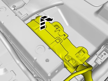
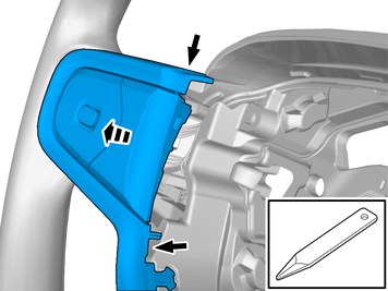
| | Release the catch. Loosen the marked detail.
|
|  | | IMG-462130 |
|
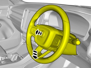
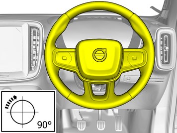
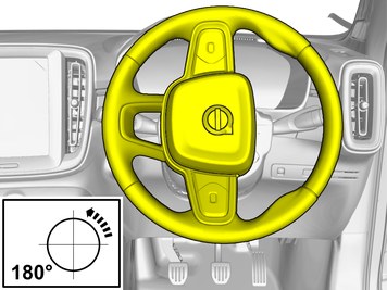
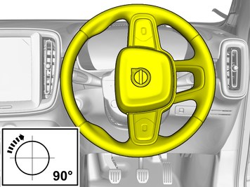
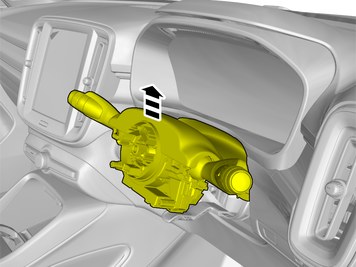
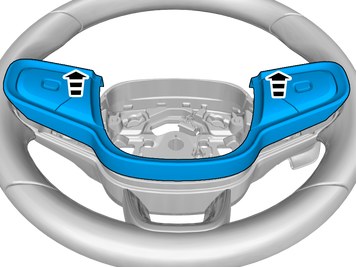
| | Turn the steering wheel into neutral position. |
|  | | IMG-462148 |
|
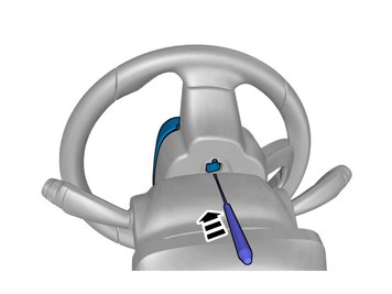
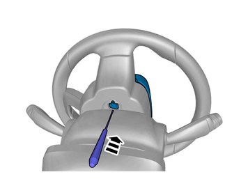
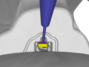
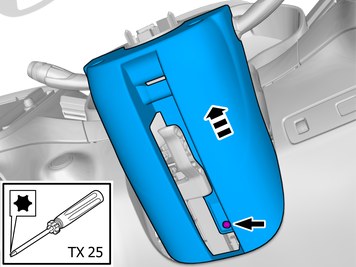
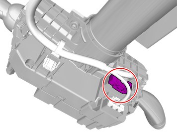
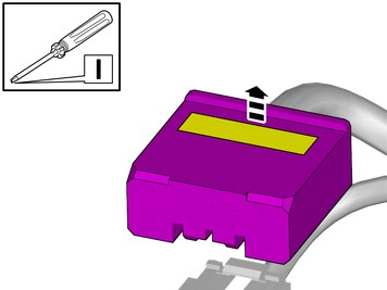
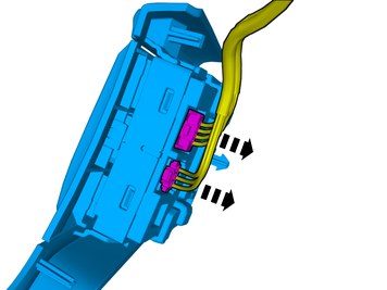
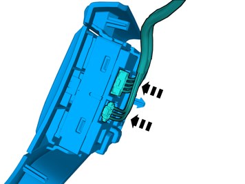
| | Warning!
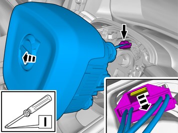
When temporarily storing a pyrotechnical component, it must always be positioned with its active part (e.g. air bag front or equivalent) facing up. |
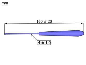
Release the connector's catch. Use: Electrician's screwdriver
Disconnect the connector. Remove the marked part. |
|  | | IMG-449866 |
|
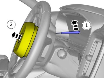
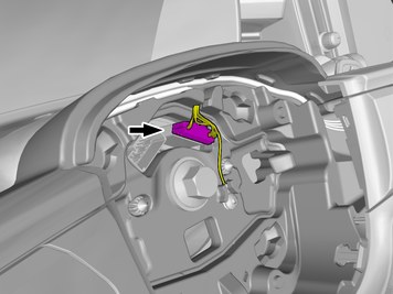
| | Disconnect the connector. |
|  | | IMG-462168 |
|
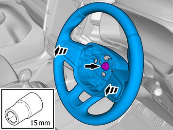
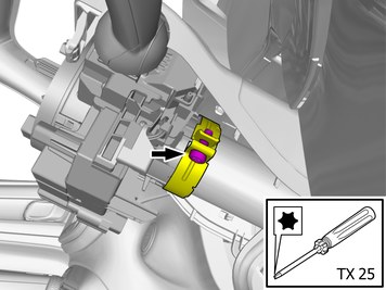
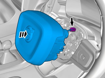
| | Remove the screw. Remove the marked part. |
|  | | IMG-449970 |
|
| | Note!
The graphic shows the back of the component before removal. |
|
|  | | IMG-449977 |
|
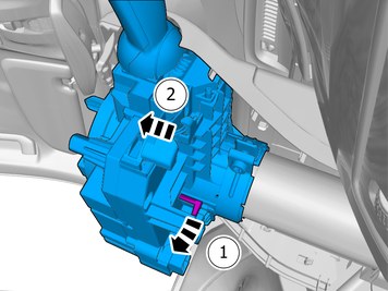
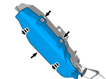
| | Release the catches. Use: Electrician's screwdriver
Loosen the marked detail. |
|  | | IMG-449978 |
|
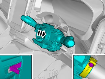
| | Remove the marked detail/details. Use: Electrician's screwdriver
|
|  | | IMG-449990 |
|
| | |
|  | | IMG-462169 |
|
| | Repeat on the other side. |
|  | | IMG-445881 |
|
| | Remove the nut. Fold marked part aside. |
|  | | IMG-462172 |
|
| | Repeat on the other side. |
|  | | IMG-462298 |
|
| | Remove the screw. Remove the marked part. |
|  | | IMG-462299 |
|
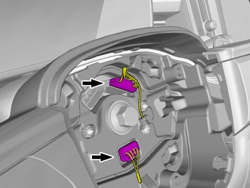
| | Disconnect the connectors. Remove the cable harness clips. |
|  | | IMG-462300 |
|
| | |
|  | | IMG-462301 |
|
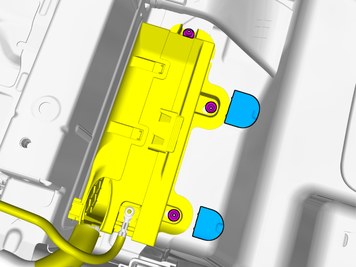
| | Release the catch. Remove the marked part. |
| | |
|  | | IMG-462302 |
|
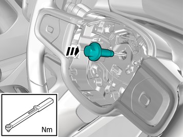
| | Caution!
Take extra care when handling the component. |
Install component that comes with the accessory kit. Tighten the screw.
Tightening torque: Steering wheel module, to Steering column
, 6 Nm
|
|  | | IMG-462296 |
|
| | Caution!
Observe caution when carrying out this step. |
|
|  | | IMG-462303 |
|
| | |
|  | | IMG-462356 |
|
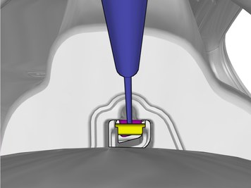
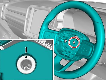
| | Release the connector's secondary lock. Lift approximately 2 mm. |
|  | | IMG-461913 |
|
| | Install component that comes with the accessory kit. |
|  | | IMG-462362 |
|
| | Route the cable harness to the existing cable harness. Install the wiring harness. Use a cable tie |
| | | IMG-462299 |
|
| | Reinstall the removed parts in reverse order. |
|  | | IMG-462368 |
|
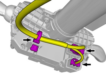
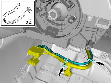
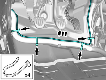
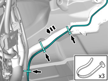
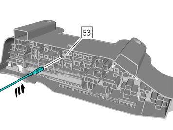
| | Position/route the cable harness as illustrated. Install the wiring harness. Use a cable tie |
|  | | IMG-462390 |
|
| | Position/route the cable harness as illustrated. |
|  | | IMG-462479 |
|
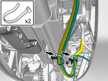
| | Caution!
Make sure to locate the wiring in such a way that contact with any moving components is avoided. |
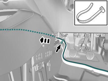
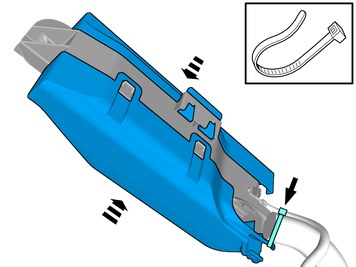
Route the cable harness to the existing cable harness. Install the wiring harness. Use a cable tie |
|  | | IMG-462481 |
|
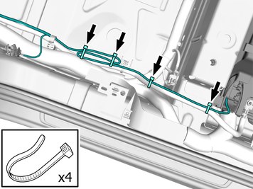
| | Route the cable harness to the existing cable harness. Install the wiring harness. Use a cable tie |
|  | | IMG-462507 |
|
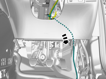
| | Pull the wiring harness through. Install the wiring harness. Use a cable tie |
|  | | IMG-462559 |
|
| | |
|  | | IMG-462560 |
|
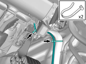
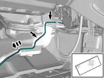
| | Position/route the cable harness as illustrated. Install the wiring harness. Use tape |
|  | | IMG-462568 |
|
| | Route the cable harness to the existing cable harness. Install the wiring harness. Use a cable tie |
|  | | IMG-462569 |
|
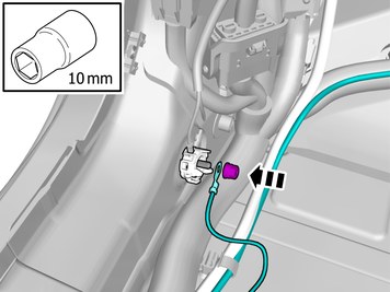
| | Remove the nut. Connect the ground cable. Install the nut.
Tightening torque: M6
, 10 Nm
|
|  | | IMG-462044 |
|
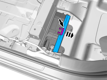
| | Release the catch. Remove the marked part. |
|  | | IMG-462045 |
|
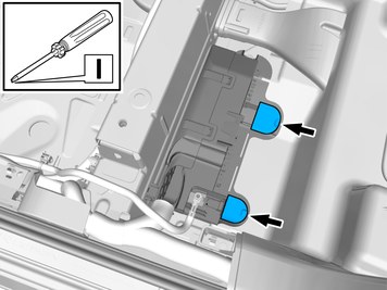
| | Remove the marked detail/details. |
|  | | IMG-462046 |
|
| | |
|  | | IMG-462268 |
|
| | |
|  | | IMG-462061 |
|
| | |
|  | | IMG-462064 |
|
| | Release the catches. Remove the marked part. |
|  | | IMG-462073 |
|
| | Connect the prerouted cable. |
|  | | IMG-462271 |
|
| | Install component that comes with the accessory kit. |
|  | | IMG-462283 |
|
| | Reinstall the removed parts in reverse order. Place the cable tie as illustrated. |
|  | | IMG-462284 |
|
| | Reinstall the removed parts in reverse order. |
|  | | IMG-462290 |
|
| | Route the cable harness to the existing cable harness. Position the cable harness excess as illustrated. Install the wiring harness. Use a cable tie |
| | |
|  | | IMG-462609 |
|
| | |
|  | | IMG-462570 |
|
| | Install the marked component. Reinstall the screw. |
|  | | IMG-462573 |
|
| | Reinstall the removed part. |
|  | | IMG-462571 |
|
| | Reinstall the removed parts in reverse order. |
| | |
|  | | IMG-436995 |
|
| | Note!
The graphic shows the back of the component before removal. |
The part is to be reused. |
|  | | IMG-437033 |
|
| | Repeat on the other side. |
|  | | IMG-437034 |
|
| | Repeat on the other side. |
|  | | IMG-437176 |
|
| | |
|  | | IMG-461777 |
|
| | Disconnect the connectors. Repeat on the other side. |
|  | | IMG-449800 |
|
| | Remove the screw. The item is to be reused. |
| | |
|  | | IMG-449870 |
|
| | Note!
Press the wire into the grove to secure it. |
Assemble components that come with the accessory kit. |
|  | | IMG-449925 |
|
| | Ground connection Position/route the cable as illustrated. Install the screw. |
|  | | IMG-461778 |
|
| | Connect the connectors. Repeat on the other side. |
|  | | IMG-449875 |
|
| | |
|  | | IMG-462165 |
|
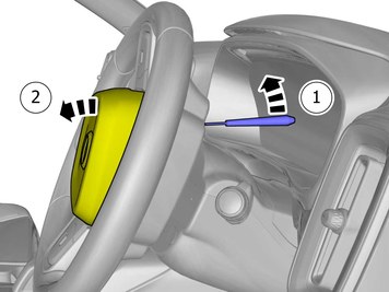
| | Note!
The markings must be opposite each other. |
Install the marked component. |
|  | | IMG-462166 |
|
| | Install component that comes with the accessory kit.
Tightening torque: Steering wheel to steering column (center screw)
, 60 Nm
|
|  | | IMG-449867 |
|
| | |
|  | | IMG-462293 |
|
| | Caution!
Ensure that the wiring harness is correctly positioned and pressed into the grooves. |
|
|  | | IMG-462575 |
|
| | Warning!
Make sure that the component has locked properly in position by pulling it towards you. |
Connect the connector. Install the marked component. |
| | |
| | | IMG-400000 |
|
| | Reinstall the removed parts in reverse order. |
|  | | IMG-400003 |
|
| | Reinstall the battery's negative cable.
Tightening torque: Battery cable for battery
, 6 Nm
|
|  | | IMG-242268 |
|
| | Download software (application) for the accessory's function according to the service information in VIDA. Order and download software according to: 32204568
|