| | |
| | Read through all of the instructions before starting installation. Notifications and warning texts are for your safety and to minimise the risk of something breaking during installation. Ensure that all tools stated in the instructions are available before starting installation. Certain steps in the instructions are only presented in the form of images. Explanatory text is also given for more complicated steps. In the event of any problems with the instructions or the accessory, contact your local Volvo dealer.
|
| | |
|  | | IMG-332179 |
|
| | Set the ignition key to position 0. Remove the battery's negative cable. |
|  | | IMG-363036 |
|
| | Note!
This colour chart displays (in colour print and electronic version) the importance of the different colours used in the images of the method steps. |
Used for focused component, the component with which you will do something. Used as extra colors when you need to show or differentiate additional parts. Used for attachments that are to be removed/installed. May be screws, clips, connectors, etc. Used when the component is not fully removed from the vehicle but only hung to the side. Used for standard tools and special tools. Used as background color for vehicle components.
|
| | |
|  | | IMG-354313 |
|
| | |
|  | | IMG-354315 |
|
| | |
|  | | IMG-354318 |
|
| | |
|  | | IMG-354319 |
|
| | |
|  | | IMG-344930 |
|
| | |
|  | | IMG-354320 |
|
| | |
|  | | IMG-349804 |
|
| | |
|  | | IMG-349806 |
|
| | |
|  | | IMG-345282 |
|
| | |
| | Cars with manual transmissions |
|  | | IMG-345747 |
|
| | Release the catch which is located inside the gear lever boot. |
| 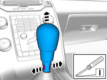 | | IMG-347222 |
|
| | |
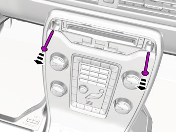
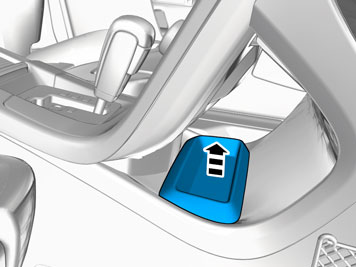
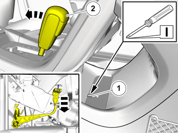
| | Cars with automatic transmissions |
|  | | IMG-345283 |
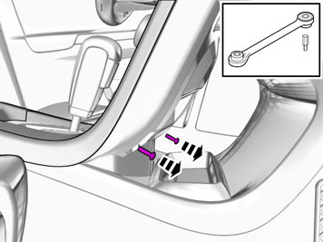
|
| | |
|  | | IMG-345284 |
|
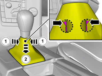
| | Release the shift-lock function. |
|  | | IMG-341878 |
|
| | |
|  | | IMG-346036 |
|
| | |
|  | | IMG-340599 |
|
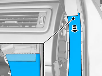
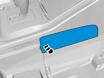
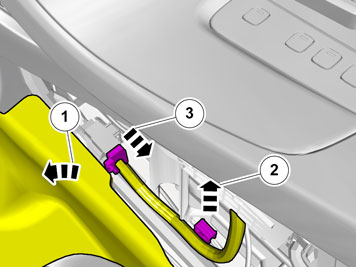
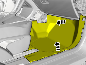
| | Fold the carpet aside. Unhook the clip(s). Disconnect the connector.
|
|  | | IMG-353601 |
|
| | |
|  | | IMG-353602 |
|
| | |
|  | | IMG-347139 |
|
| | |
| | Vehicles with the 4C system. |
|  | | IMG-345317 |
|
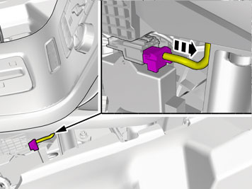
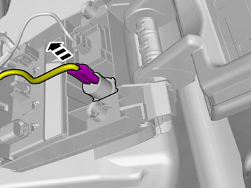
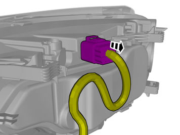
| | Disconnect the connector. |
| | |
|  | | IMG-349826 |
|
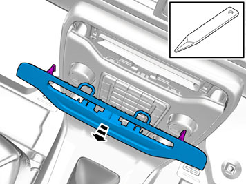
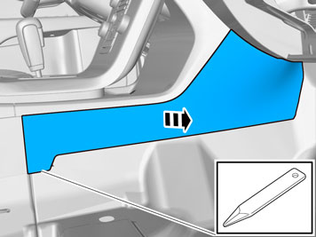
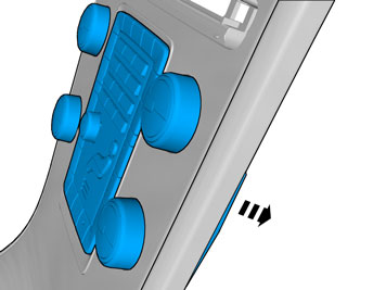
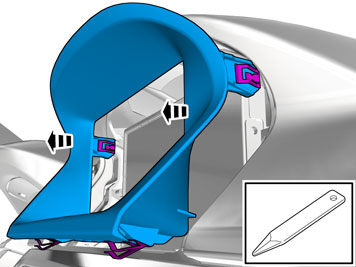
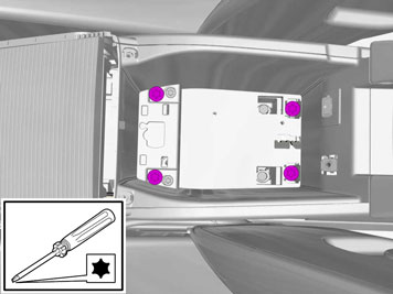
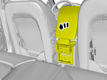
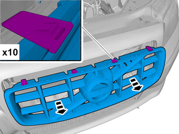
| | Caution!
Be careful not to damage the catches. |
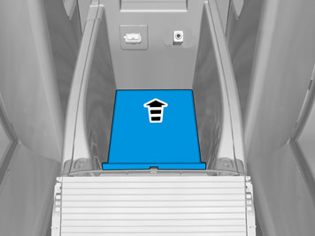
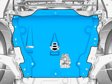
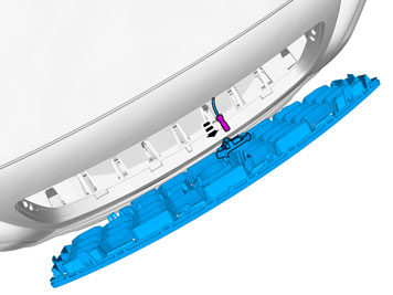
Remove the panel. |
|  | | IMG-340605 |
|
| | |
|  | | IMG-345296 |
|
| | |
|  | | IMG-380815 |
|
| | |
| | |
|  | | IMG-380819 |
|
| | |
|  | | IMG-380816 |
|
| | |
| | |
|  | | IMG-349942 |
|
| | |
|  | | IMG-349946 |
|
| | |
|  | | IMG-353492 |
|
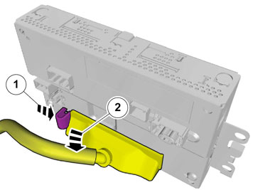
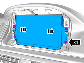
| | Disconnect the connectors. |
|  | | IMG-349876 |
|
| | |
|  | | IMG-349877 |
|
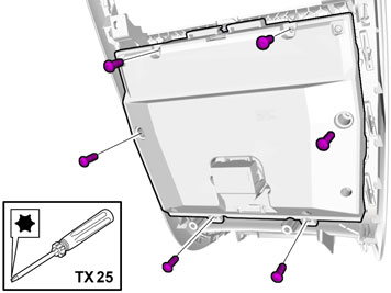
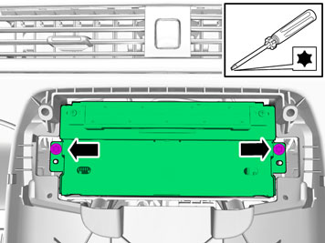
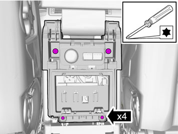
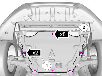
| | Remove the screws. Remove the panel. |
|  | | IMG-349901 |
|
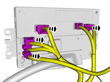
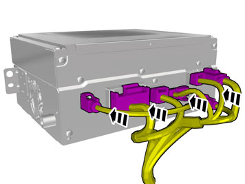
| | Caution!
The number of connectors can vary depending on the vehicle's equipment level. |
Disconnect the connectors. |
|  | | IMG-349903 |
|
| | |
|  | | IMG-353512 |
|
| | |
|  | | IMG-353511 |
|
| | |
|  | | IMG-349993 |
|
| | |
|  | | IMG-350006 |
|
| | |
|  | | IMG-352301 |
|
| | Remove the screws. On both sides. |
|  | | IMG-352271 |
|
| | |
|  | | IMG-350026 |
|
| | |
|  | | IMG-349999 |
|
| | |
|  | | IMG-349992 |
|
| | Disconnect the connector. |
| | |
|  | | IMG-350072 |
|
| | |
|  | | IMG-355161 |
|
| | Caution!
Make sure that no part of the wiring harness is trapped. |
Facilitate cable routing by temporarily raising the floor bracket using a socket or similar. Pull the wiring through. |
|  | | IMG-355174 |
|
| | |
|  | | IMG-355175 |
|
| | Tear off the excess foam tape. |
|  | | IMG-355200 |
|
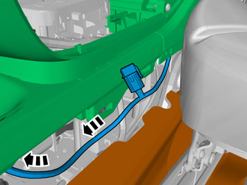
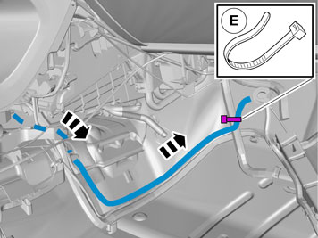
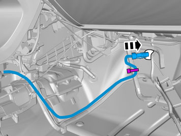
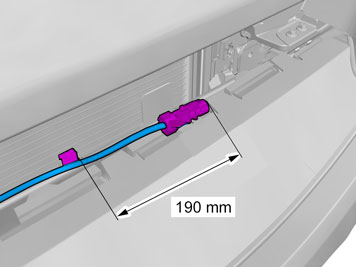
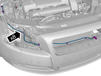
| | Route the cable harness to the existing cable harness. |
|  | | IMG-345857 |
|
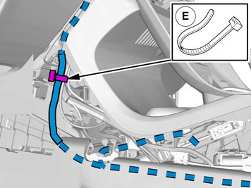
| | Route the cable harness to the existing cable harness. Install the cable. Pull the wiring through. |
|  | | IMG-355206 |
|
| | |
|  | | IMG-345863 |
|
| | |
|  | | IMG-349904 |
|
| | |
| | |
|  | | IMG-352186 |
|
| | |
|  | | IMG-352187 |
|
| | |
|  | | IMG-353339 |
|
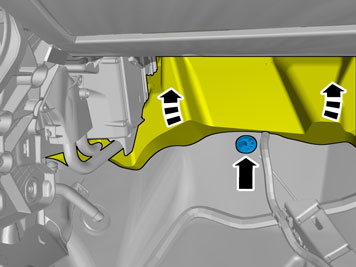
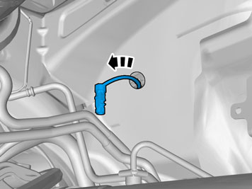
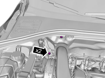
| | Fold the insulation aside. Locate the rubber grommet under the insulation and press it out. |
| | |
|  | | IMG-345859 |
|
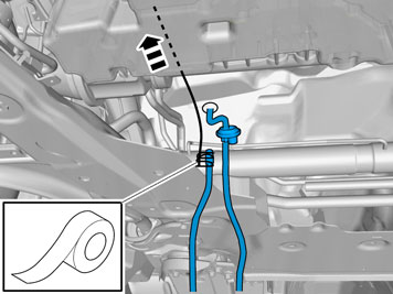
| | Note!
Do not yet tighten the clamps. |
Route the cable harness to the existing cable harness. |
|  | | IMG-345860 |
|
| | |
| | |
|  | | IMG-353491 |
|
| | |
|  | | IMG-349948 |
|
| | |
| | | IMG-349942 |
|
| | |
| | |
|  | | IMG-345877 |
|
| | Remove the clips. Remove the screws. |
|  | | IMG-345878 |
|
| | |
|  | | IMG-345879 |
|
| | Note!
On some markets the rubber grommet may be covered by the heat shield. |
|
| | |
|  | | IMG-345880 |
|
| | |
|  | | IMG-345881 |
|
| | |
|  | | IMG-353681 |
|
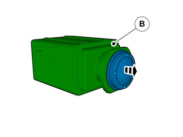
| | Caution!
Take extra care when handling the component. |
Pull the wiring through. Use: 1161427, Low temperature grease
|
|  | | IMG-345883 |
|
| | |
| | |
|  | | IMG-353376 |
|
| | |
|  | | IMG-353377 |
|
| | |
|  | | IMG-353378 |
|
| | |
|  | | IMG-353381 |
|
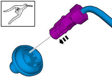
| | Disconnect the connector. |
|  | | IMG-354328 |
|
| | |
|  | | IMG-273585 |
|
| | |
|  | | IMG-340533 |
|
| | |
| | |
|  | | IMG-340606 |
|
| | |
|  | | IMG-345884 |
|
| | |
|  | | IMG-345885 |
|
| | Caution!
Make sure to locate the wiring in such a way that any damage caused by heat or excessive wear is avoided. |
Note!
Do not yet tighten the clamps. |
Route the cable harness to the existing cable harness. |
| 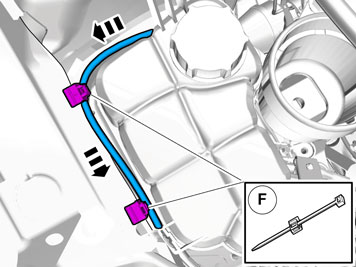 | | IMG-345886 |
|
| | Note!
Do not yet tighten the clamps. |
|
|  | | IMG-345887 |
|
| | Note!
Do not yet tighten the clamps. |
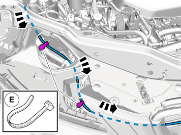
Route the cable harness to the existing cable harness. |
|  | | IMG-353446 |
|
| | Note!
Do not yet tighten the clamps. |
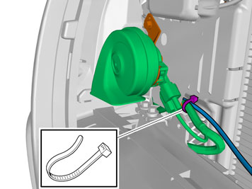
Route the cable harness to the existing cable harness. |
|  | | IMG-353447 |
|
| | Note!
Do not yet tighten the clamps. |
|
|  | | IMG-345889 |
|
| | |
|  | | IMG-340544 |
|
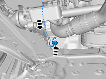
| | Caution!
Make sure to locate the wiring in such a way that any damage caused by heat or excessive wear is avoided. |
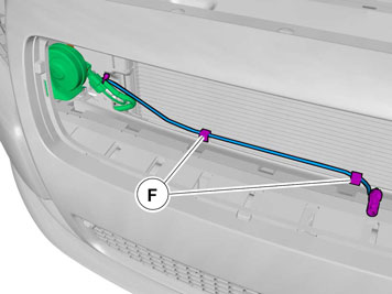
Insert the cable in to the passenger compartment, adjust the cable length out into the engine compartment and secure the rubber grommet. |
|  | | IMG-354476 |
|
| | Caution!
Tighten clamps properly. |
|
|  | | IMG-347781 |
|
| | |
|  | | IMG-347786 |
|
| | |
|  | | IMG-376589 |
|
| | |
|  | | IMG-376680 |
|
| | |
|  | | IMG-376597 |
|
| | |
|  | | IMG-376613 |
|
| | |
|  | | IMG-336901 |
|
| | Reinstall the removed parts in reverse order. Reinstall the battery's negative cable. |
|  | | IMG-242268 |
|
| | Download software (application) for the accessory's function according to the service information in VIDA. Order and download software according to: 31288598
|