| | |
|  | | IMG-332058 |
|
|  | | IMG-332059 |
|
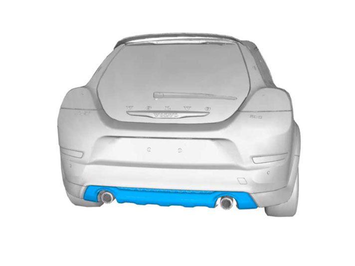
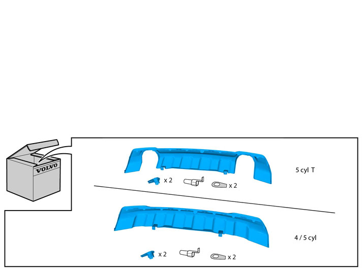
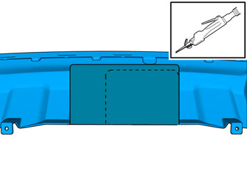
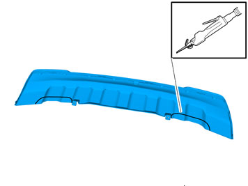
| | A Applies to cars with a tow hitch Take the Skid plate from the kit. Saw out the new Skid plate according to the markings. Remove the shaded area Tape the outside to prevent the saw foot from damaging the paint
Note!
Take extra care not to damage the painted surface of the components. |
Smooth off the sawn edges with a fine toothed file.
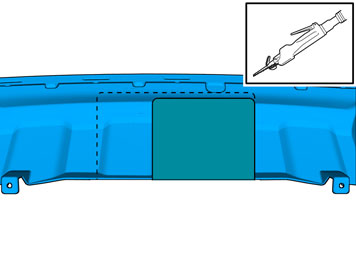
A Detachable towbar B Fixed towbar B |
|  | | IMG-332060 |
|
| | Applies to cars with diesel engine D4164TX and 5-cyl petrol engines without turbo |
|  | | IMG-332061 |
|
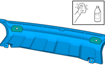
| | Applies to cars with parking assistance |
|  | | IMG-297085 |
|
| | Clean using isopropanol. Allow to dry.
|
|  | | IMG-297086 |
|
| | |
|  | | IMG-297087 |
|
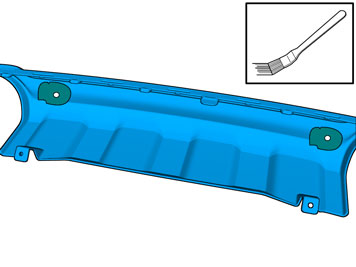
| | Paint the sensors with colour code 426. Only apply one layer.
Caution!
Protect the connection's contact surfaces from paint. Too many layers of paint can result in the function partially or totally disappearing. |
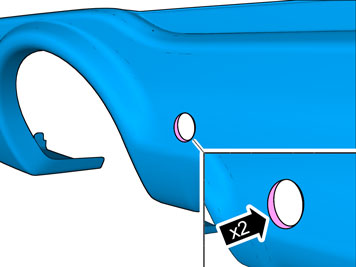
When the paint has dried, reinstall the sealing rings.
|
|  | | IMG-332062 |
|
| | |
|  | | IMG-332063 |
|
| | |
|  | | IMG-332064 |
|
| | |
|  | | IMG-332066 |
|
| | |
|  | | IMG-332073 |
|
| | |
|  | | IMG-254261 |
|
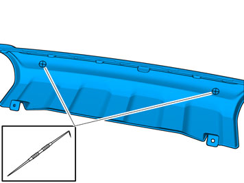
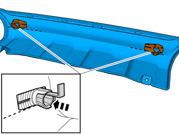
| | Take the 2 holders from the kit. Clean the surfaces as illustrated using a cleaning cloth P/N 9192678. Allow to dry. Apply a thin and even layer of activator, part no. 8637076, on the cleaned surfaces and allow to dry for at least 10 min.
|
|  | | IMG-332074 |
|
| | |
|  | | IMG-332075 |
|
|  | | IMG-332076 |
|
| | |
|  | | IMG-240963 |
|
| | |
|  | | IMG-240964 |
|
| | |
|  | | IMG-332077 |
|
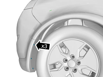
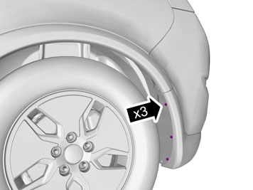
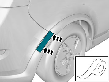
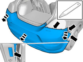
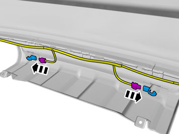
| | Attach a piece of tape to the wing extender's rear section to protect it when removing the bumper cover at the front edge. The tape must be positioned so as not to leave any marks when prying the bumper loose. Carry out the procedure on both sides of the car.
|
|  | | IMG-332078 |
|
|  | | IMG-240974 |
|
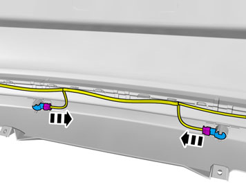
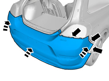
| | A Illustration B Disconnect the connector for the license plate lighting, on the left-hand side. If the car has rear parking assistance, disconnect the connector on the right-hand side. Remove the pieces of tape.
|
|  | | IMG-332079 |
|
| | Applies to cars with parking assistance |
|  | | IMG-332080 |
|
| | |
|  | | IMG-332081 |
|
| | |
|  | | IMG-332082 |
|
| | Applies to all models Note!
Take extra care when working with the bumper cover and Skid plate. |
|
|  | | IMG-332083 |
|
| | Applies to cars with parking assistance |
|  | | IMG-246008 |
|
| | |
|  | | IMG-332088 |
|
|  | | IMG-332100 |
|
| | |
|  | | IMG-332101 |
|
| | |
|  | | IMG-332102 |
|
| | |
|  | | IMG-332104 |
|
| | |
|  | | IMG-332123 |
|
| | |
|  | | IMG-332124 |
|
| | Applies to cars with parking assistance |
|  | | IMG-332125 |
|
| | |
|  | | IMG-332126 |
|
| | |
|  | | IMG-241381 |
|
|  | | IMG-332127 |
|
| | |
|  | | IMG-246794 |
|
| | |
|  | | IMG-241386 |
|
| | |
| | | IMG-332075 |
|
| | | IMG-332076 |
|
| | |
|  | | IMG-242268 |
|
| | |