| | |
|  | | R8902382 |
|
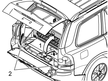
| | Preparations Fold up the centre rear floor hatch (1). If the floor hatch is equipped with a grocery bag holder on the underside then it is fixed with a strap on each short side of the storage box, and these must be detached. Remove the storage box underneath and lift it out. Remove the side floor hatches (2) on the right and left-hand sides in the cargo compartment. If the car is equipped with a spare wheel, remove it.
|
|  | | IMG-216340 |
|
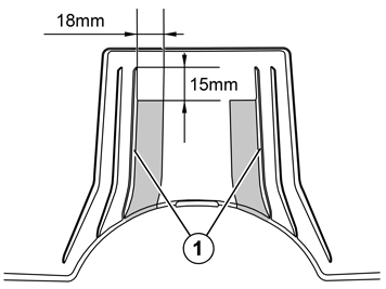
| | Raise the car. Measure out and draw a horizontal line 15 mm (9/16") under the top edge of the grooves (1), on the inside of the rear bumper cover. Draw a vertical line 18 mm (11/16) from the inside of the grooves (1). Cut/saw along the drawn lines so that two parallel slits are formed in the bumper cover. Smooth off all edges with a file.
|
|  | | R8902815 |
|
| | |
|  | | R8902814 |
|
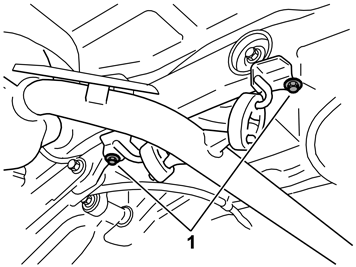
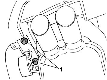
| | Detach the rubber mounting (1). Detach the silencer's rear mounting bracket from the lower edge of the left-hand side member by removing the screws (2). Carefully bend aside the heat deflector plate at the side member to make more space to work in.
|
|  | | R8601029 |
|
|  | | R8601030 |
|
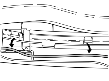
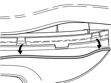
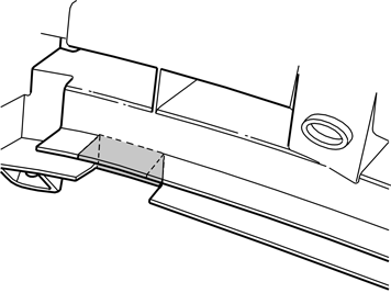
| | Applies to cars with rear parking assistance Illustration A shows the right-hand side of the bumper Illustration B shows the left-hand side of the bumper |
|  | | R8601042 |
|
| | |
|  | | IMG-218664 |
|
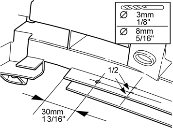
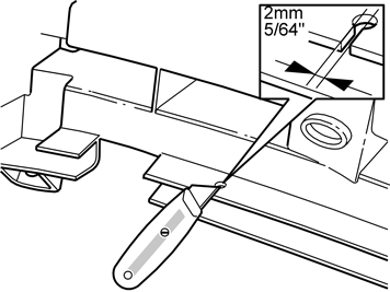
| | Applies to cars with rear parking assistance Right-hand side: Measure out for drilling the hole for the cable grommet in the upper of the rear section's plates as illustrated. Pre-drill using a Ø3 mm (1/8") diameter drill bit, and then drill out the hole to Ø8 mm (5/16"). Use an angle drilling machine and short drill bits.
|
|  | | R8601044 |
|
| | |
|  | | R8601045 |
|
| | |
|  | | R8601046 |
|
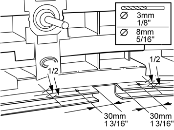
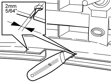
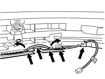
| | Applies to cars with rear parking assistance Left-hand side: Measure out for drilling the hole for the cable grommet on the right and left-hand sides of the cut-out, in the upper of the rear section's plates as illustrated. Pre-drill using a Ø3 mm (1/8") diameter drill bit, and then drill out the holes to Ø8 mm (5/16"). Use an angle drilling machine and short drill bits.
|
|  | | R8601047 |
|
| | |
|  | | R8601049 |
|
| | |
|  | | R8601048 |
|
| | |
| | Installing the towing member |
|  | | IMG-217922 |
|
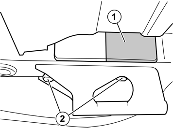
| | Installing the towing member Applies to all models Lift up the protective tags (1) (at the rear edge) which cover the mounting holes on the inside of the side members (one on each side) and cut away 80 mm. Remove the bracket for the towing eye by removing the screws (2). Remove any sealing compound from the surface where the end faces of the towing member shall be located.
|
|  | | IMG-308203 |
|
|  | | IMG-308204 |
|
|  | | IMG-308205 |
|
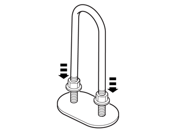
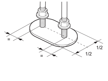
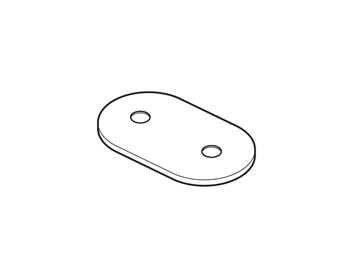
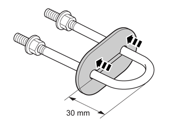
| | Illustration A Get a brace and a foam rubber plate from the kit. Centre the brace on the plate and press, so that the threaded ends leave an imprint on the plate
Illustration B Illustration C |
|  | | IMG-308206 |
|
| | |
|  | | IMG-308207 |
|
| | |
|  | | IMG-308208 |
|
| | |
|  | | IMG-308209 |
|
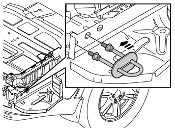
| | Lower the car. Remove the protective tags which cover the mounting holes on the outside of the side members. Fit the mounting bracket through the two rear holes in the outer wall of the side member. The threaded sections of the mounting bracket should now protrude through to the underside of the car. Repeat on the other side. Secure the mounting brackets using butyl tape for example in order to prevent them from falling back.
|
|  | | IMG-216360 |
|
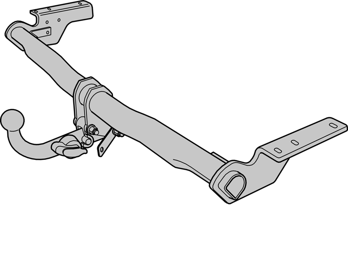
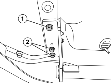
| | Raise the car. Remove the towbar from the towing member, see the handling instructions for detachable towbar. Lift up the towing member. Start by angling up the left-hand side's end face above the silencer's end pipe and up behind the bumper to the side member. Following which, angle up the right-hand side's end face to the side member, and position it on the side members, opposite their holes. Fit the M12x40 screw (1) in the front hole on each side, while holding the towing member in position. Install the remaining screws (2). Insert the screws all the way without tightening them.
Note!
Apply rustproofing agent under the car and on the side members around the end faces, scraping away any sealing compound, before torque tightening the screws. |
|
|  | | IMG-217924 |
|
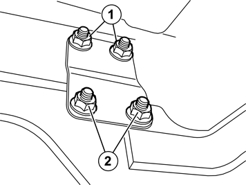
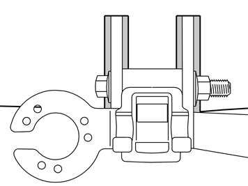
| | Install the reinforcing plate with the oval holes facing up. Install the flange nuts (1) on the mounting bracket. Install the bolts and the flange nuts (2). Insert the screws all the way without tightening them. Carry out the above procedure on the other side too.
|
|  | | IMG-216400 |
|
| | |
|  | | IMG-217925 |
|
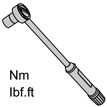
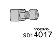
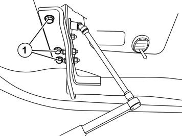
| | Torque tighten the screws (1) to 120 Nm on both sides. Torque tighten the upper and lower bolted joint for the mounting bracket to 50 Nm. Use joint socket (P/N 9814017) when tightening the upper one. Repeat on the other side. Bend back the heat deflector plate. Reinstall the silencer's rear mounting. Reinstall the silencer's front mounting. Torque tighten the screws to 24 Nm.
|
|  | | IMG-308210 |
|
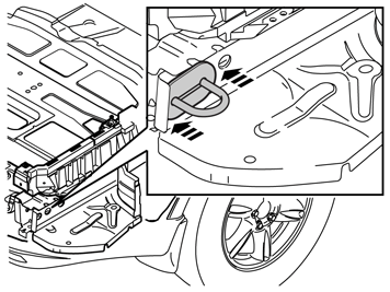
| | Remove the pieces of butyl tape, if used to secure the brace. Press on the foam rubber plate against the side member so that it seals tightly around the holes. Repeat the operation on the other side.
|
|  | | IMG-216442 |
|
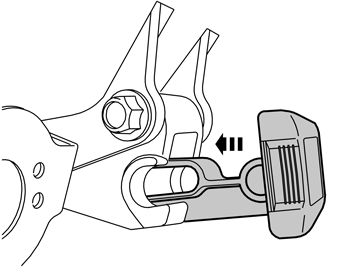
| | Check the function of the detachable towbar. Install the protective plug. Fit the towbar wiring in accordance with the separate installation instructions.
|
| | |
|  | | IMG-218360 |
|
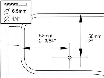
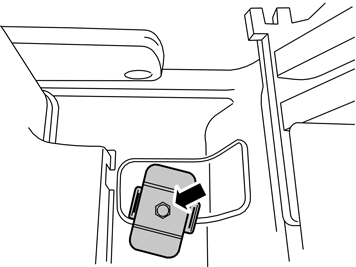
| | Installing the holder Measure out for drilling the hole for the towbar holder, to the right of the battery as illustrated. Use a Ø6.5 mm (1/4") diameter drill bit.
Note!
Remove any spare wheel before drilling. |
Remove any swarf. Apply rustproofing agent to the hole.
|
|  | | IMG-218361 |
|
| | |
|  | | IMG-218362 |
|
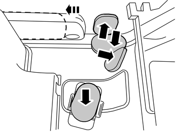
| | Applies to cars with warning triangle Move the warning triangle approx. 80 mm sideways into the centre to make space for the towbar. Mark out the inner wall locations for the warning triangle's Velcro fasteners. Secure two Velcro fasteners at the markings on the inner wall. Install the warning triangle.
|
| | |
|  | | IMG-218363 |
|
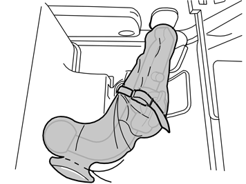
| | Storing the towbar Take the retaining strap and thread it through the holder's two eyelets. Thread the accompanying protective bag over the towbar and tighten the protective bag's cord. Position the towbar with bag in the holder with the ball section to the rear, and tighten with the strap.
|
| | |
| | Finishing work Put the spare wheel back in place. Reinstall the storage box and floor hatches. Affix the accompanying decal to the underside of the floor hatch, as illustrated. Fill in the registration card and send it to the local Volvo dealer.
|

