| | |
| | Read through all of the instructions before starting installation. Notifications and warning texts are for your safety and to minimise the risk of something breaking during installation. Ensure that all tools stated in the instructions are available before starting installation. Certain steps in the instructions are only presented in the form of images. Explanatory text is also given for more complicated steps. In the event of any problems with the instructions or the accessory, contact your local Volvo dealer.
|
| | |
| | After installation, the car must not be driven for 2 hours After installation, the car must not be washed for 48 hours When installing, the car must retain a temperature of 20 degrees C. |
| 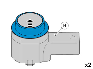 | | IMG-340635 |
|
| | |
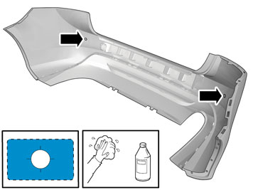
| 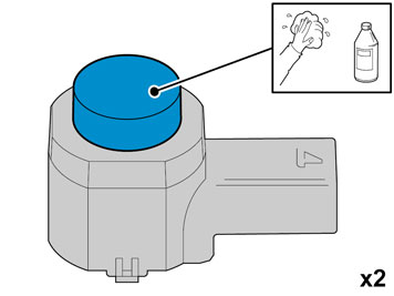 | | IMG-344142 |
|
| | Use: 1161721, Isopropanol
|
| 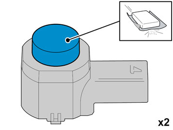 | | IMG-344141 |
|
| | Matt the surface gently. Use: , Sand paper P1000
|
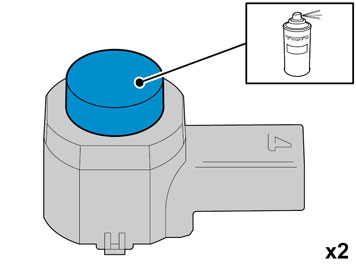
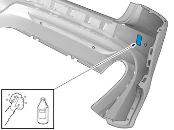
| | | IMG-344142 |
|
| | Use: 1161721, Isopropanol
Do not touch the surface. |
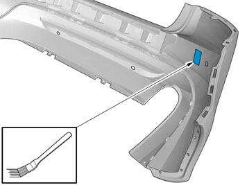
|  | | IMG-344251 |
|
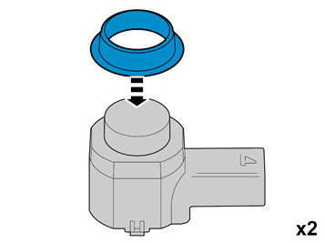
| | Caution!
Protect connector surfaces against paint spray. |
Note!
Paint the sensors the same colour code as the vehicle. |
Use: , Volvo Original Touch-up paint
Use base coat only. Use: 31335447, Varnish 2-component
Also see the instructions on the container. |
|  | | IMG-333934 |
|
| | Caution!
First the paint must dry after painting. |
|
|  | | IMG-332193 |
|
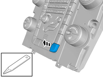
| | Set the ignition key to position 0. |
|  | | IMG-340598 |
|
| | |
|  | | IMG-340599 |
|
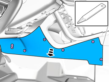
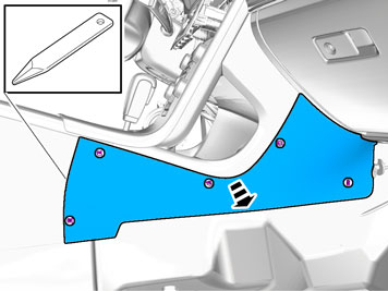
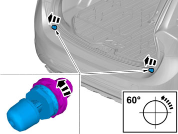
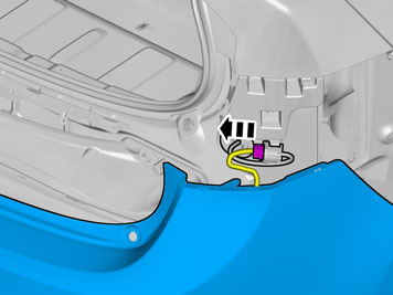
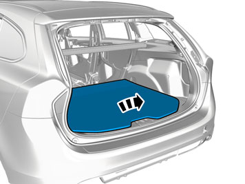
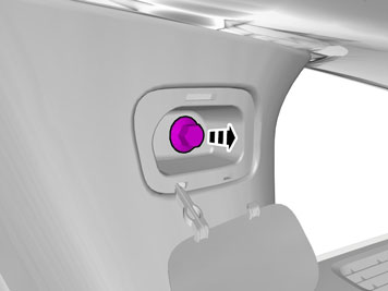
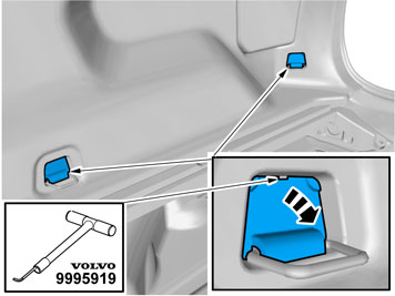
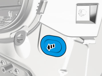
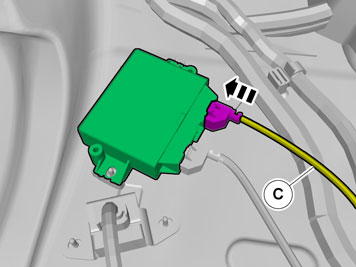
| | Fold the carpet to the side. Remove the cable harness clips. Disconnect the connector. |
|  | | IMG-340600 |
|
| | |
| | Vehicles with the 4C system. |
|  | | IMG-340601 |
|
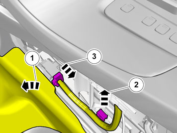
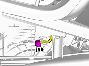
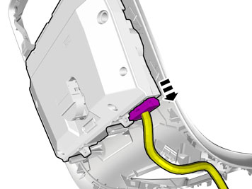
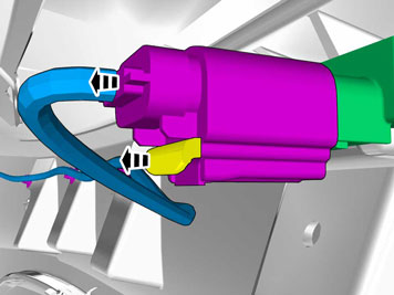
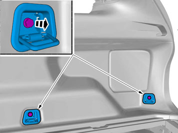
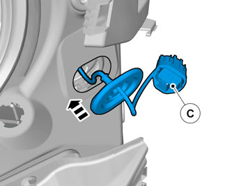
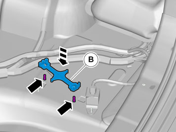
| | Disconnect the connector. |
| | |
|  | | IMG-340983 |
|
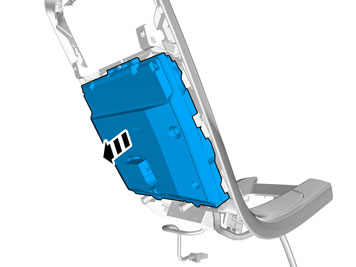
| | |
|  | | IMG-340984 |
|
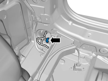
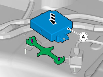
| | Disconnect the connector. |
|  | | IMG-340985 |
|
| | |
|  | | IMG-340987 |
|
| | |
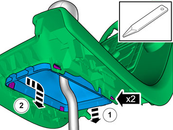
| | Cars with automatic transmissions |
|  | | IMG-340596 |
|
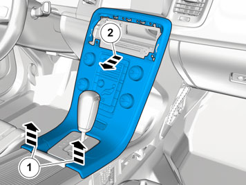
| | |
|  | | IMG-293007 |
|
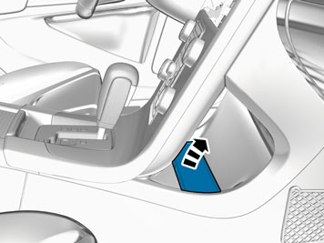
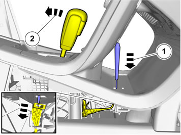
| | Release the shift-lock function. Move the gear lever to D. |
| | Cars with manual transmissions |
|  | | IMG-345292 |
|
| | |
| | |
|  | | IMG-340981 |
|
| | |
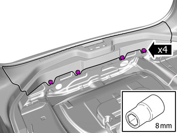
|  | | IMG-340604 |
|
| | |
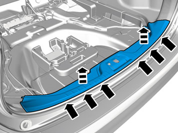
|  | | IMG-340636 |
|
| | |
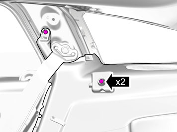
|  | | IMG-340637 |
|
| | |
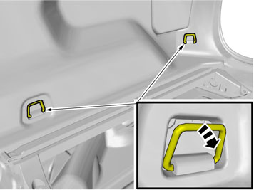
|  | | IMG-340638 |
|
| | |
|  | | IMG-340639 |
|
| | |
| | Reinstall the removed parts in reverse order. |
|  | | IMG-346181 |
|
| | |
|  | | IMG-347593 |
|
| | |
| | |
|  | | IMG-340640 |
|
| | |
|  | | IMG-346169 |
|
| | |
|  | | IMG-346177 |
|
| | Repeat the steps when removing on opposite side. |
|  | | IMG-346178 |
|
| | |
| | Vehicles with keyless entry |
|  | | IMG-346370 |
|
| | |
|  | | IMG-340645 |
|
| | |
|  | | IMG-340646 |
|
| | |
| | |
|  | | IMG-349422 |
|
| | |
|  | | IMG-349423 |
|
| | |
|  | | IMG-349316 |
|
| | |
|  | | IMG-349327 |
|
| | |
|  | | IMG-349328 |
|
| | |
|  | | IMG-349329 |
|
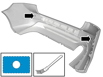
| |
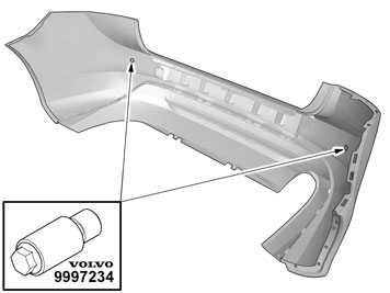
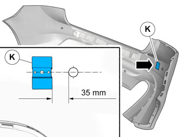
Use special tool: T9997234, Hole stamp
|
|  | | IMG-349330 |
|
| | Clean the surfaces. Allow to dry. Use: 1161721, Isopropanol
|
|  | | IMG-341991 |
|
| | Clean the surface. Allow to dry. Use: 1161721, Isopropanol
|
|  | | IMG-349331 |
|
| | Clean the surface. Allow to dry. Use: 1161721, Isopropanol
|
|  | | IMG-349334 |
|
| | Apply a thin and even layer. Allow to dry for at least 10 minutes. Use: 8637076, Activator
|
|  | | IMG-341992 |
|
| | Apply a thin and even layer. Allow to dry for at least 10 minutes. Use: 8637076, Activator
|
|  | | IMG-349335 |
|
| | Apply a thin and even layer. Allow to dry for at least 10 minutes. Use: 8637076, Activator
|
|  | | IMG-344986 |
|
| | |
|  | | IMG-347917 |
|
| | |
|  | | IMG-343412 |
|
| | |
|  | | IMG-343413 |
|
| | |
|  | | IMG-343415 |
|
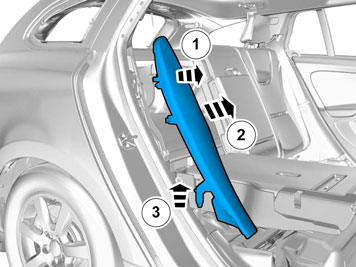
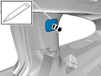
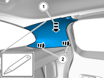
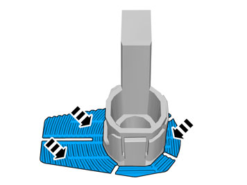
| | Release the lock. Repeat on the other side. |
|  | | IMG-343416 |
|
| | |
|  | | IMG-343418 |
|
| | |
|  | | IMG-343417 |
|
| | |
|  | | IMG-343420 |
|
| | |
|  | | IMG-343421 |
|
| | |
|  | | IMG-343422 |
|
| | |
|  | | IMG-343423 |
|
| | |
|  | | IMG-343424 |
|
| | |
|  | | IMG-307608 |
|
| | |
|  | | IMG-307609 |
|
| | |
|  | | IMG-347610 |
|
| | |
|  | | IMG-343425 |
|
| | |
| | Vehicles with keyless entry |
|  | | IMG-346381 |
|
| | |
|  | | IMG-346386 |
|
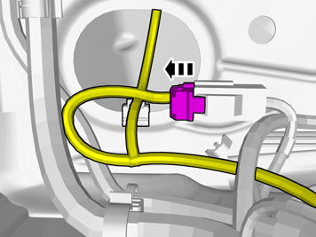
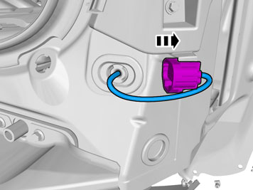
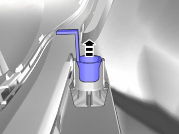
| | Disconnect the connector. |
|  | | IMG-346387 |
|
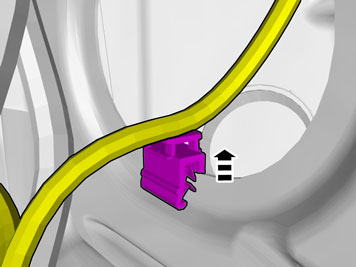
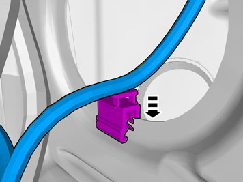
| | Unhook the cable harness clips. |
|  | | IMG-346391 |
|
| | |
|  | | IMG-346396 |
|
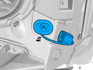
| | The part is not to be reused. |
| | Vehicles without keyless entry |
|  | | IMG-348661 |
|
| | |
| | |
|  | | IMG-346411 |
|
| | |
|  | | IMG-346416 |
|
| | |
|  | | IMG-340668 |
|
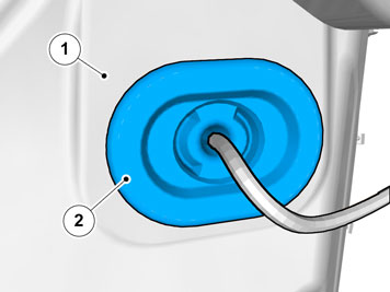
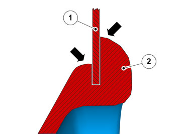
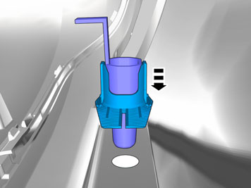
| | Caution!
Make sure that the rubber grommet seals properly to the body. |
|
|  | | IMG-346421 |
|
| | |
|  | | IMG-346431 |
|
| | |
| | Vehicles without keyless entry |
|  | | IMG-346466 |
|
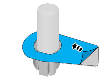
| | Tear off the excess foam tape. |
| | Vehicles with keyless entry |
|  | | IMG-346472 |
|
| | |
| | |
|  | | IMG-346506 |
|
| | |
|  | | IMG-346511 |
|
| | |
|  | | IMG-346516 |
|
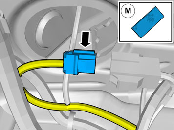
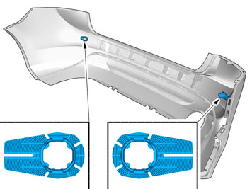
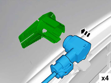
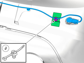
| | Locate the existing connector in the vehicle's cable harness. |
|  | | IMG-346521 |
|
| | |
|  | | IMG-346523 |
|
| | |
|  | | IMG-340682 |
|
| | |
|  | | IMG-340686 |
|
| | |
|  | | IMG-349351 |
|
| | |
|  | | IMG-340689 |
|
| | Note!
Prepare and install one holder at a time. |
|
|  | | IMG-340690 |
|
| | |
|  | | IMG-349352 |
|
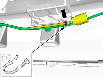
| | Note position of components. |
|  | | IMG-340692 |
|
| | |
|  | | IMG-340694 |
|
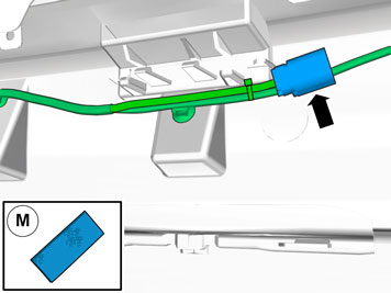
| | Note!
Ensure that the tape is fixed to the surface. |
|
|  | | IMG-340695 |
|
| | |
|  | | IMG-340696 |
|
| | Put the wiring in the Bumper cover without installing the wiring. |
|  | | IMG-340697 |
|
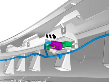
| | Connect the two painted sensors to the external connections. |
|  | | IMG-340698 |
|
| | |
|  | | IMG-349397 |
|
| | |
|  | | IMG-349401 |
|
| | |
|  | | IMG-349403 |
|
| | |
|  | | IMG-340702 |
|
| | |
| | Vehicles without keyless entry |
|  | | IMG-348276 |
|
| | |
|  | | IMG-342949 |
|
| | Tear off the excess foam tape. |
| | Vehicles with keyless entry |
|  | | IMG-340705 |
|
| | |
| | |
|  | | IMG-346526 |
|
| | |
| | Reinstall the removed parts in reverse order. |
|  | | IMG-242268 |
|
| | Download software (application) for the accessory's function according to the service information in VIDA. See VIDA or the accessories catalogue for software part number. |