| | |
|  | | IMG-316263 |
|
| | |
|  | | IMG-331109 |
|
| | |
|  | | IMG-331110 |
|
| | |
|  | | IMG-231547 |
|
| | |
|  | | IMG-231549 |
|
| | |
|  | | IMG-231550 |
|
| | |
|  | | IMG-231551 |
|
| | |
|  | | IMG-231552 |
|
| | |
|  | | IMG-231559 |
|
| | |
|  | | IMG-231560 |
|
| | |
|  | | IMG-231563 |
|
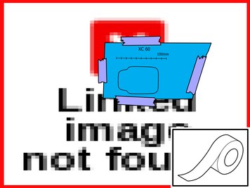
| | Take a sharp knife. First make a thin cut along the edges of the inside of the template. This provides a groove to follow. Then cut carefully out the bumper cover.
Note!
Cut carefully. It is easy to slip with the knife and move outside the template. |
Remove the template and tape pieces. Install the protective cover for the front engine block heater socket from the kit. Check that it aligns. Adjust the hole using a knife or file as necessary. Smooth off the hole edges. Remove any swarf.
|
|  | | IMG-265066 |
|
| | |
|  | | IMG-265067 |
|
| | |
|  | | IMG-265068 |
|
| | Take a sharp knife. First make a thin cut along the edges of the inside of the template. This provides a groove to follow. Then cut carefully out of the bumper cover.
Note!
Cut carefully. It is easy to slip with the knife and move outside the template. |
Remove the template. Install the protective cover for the front engine block heater socket from the kit. Check that it aligns. Adjust the hole using a knife or file as necessary. Smooth off the hole edges. Remove any swarf.
|
|  | | IMG-290483 |
|
| | |
|  | | IMG-290484 |
|
| | |
|  | | IMG-290964 |
|
| | |
| | | IMG-231563 |
|
| | Take a sharp knife. First make a thin cut along the edges of the inside of the template. This provides a groove to follow. Then cut carefully out of the bumper cover.
Note!
Cut carefully. It is easy to slip with the knife and move outside the template. |
Remove the template. Install the protective cover for the front engine block heater socket from the kit. Check that it aligns. Adjust the hole using a knife as necessary. Smooth off the hole edges. Remove any swarf.
|
|  | | IMG-231564 |
|
| | Applies to all models Press the protective cover (from the kit) into place in the hole cut in the bumper cover. Take the cable for the front engine block heater socket with ground lead from the kit and thread them through the protective cover.
|
|  | | IMG-231566 |
|
|  | | IMG-231565 |
|
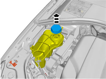
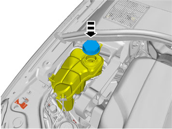
| | Illustrations A and B Install the attaching brace and nut from the kit. Rotate the connector for the front engine block heater socket carefully so that the cover opens backwards (Illustration B). Plug the electrical connector into the front engine block heater socket. Use the connector as a counterhold when tightening. Tighten the front engine block heater socket to the bumper shell. Press the cable into the holder on the washer fluid reservoir. Remove the cover on the radiator expansion tank.
|
|  | | IMG-231309 |
|
| | |
|  | | IMG-231567 |
|
|  | | IMG-231568 |
|
| | |
|  | | IMG-231571 |
|
|  | | IMG-332449 |
|
| | Illustration A Applies to the S80 and V70 Drill a Ø 4mm (Ø 5/32 ") hole for the front intake grounding on the underside of the left front side member as illustrated. Deburr the hole edges, remove the drill swarf and apply rustproofing agent. Take a screw and toothed washer from the kit. Tighten the ground cable.
Illustration B Applies to the XC60 Drill a Ø 4mm (Ø 5/32 ") hole for the front intake grounding on the inside of the left front side member as illustrated. Deburr the hole edges, remove the drill swarf and apply rustproofing agent. Take a screw and toothed washer from the kit. Tighten the ground cable.
|
| | Installing the engine block heater |
|  | | IMG-279168 |
|
| | Installing the engine block heater |
|  | | IMG-331126 |
|
| | |
|  | | IMG-331128 |
|
| | |
|  | | IMG-331133 |
|
| | |
|  | | IMG-331134 |
|
| | |
|  | | IMG-331135 |
|
|  | | IMG-331136 |
|
| | Illustrations A and B Cut the hose (1) as follows: Measure out for cutting the coolant hose between the oil cooler and the thermostat housing. Position the hose at the heater's lower connection, ensure that it runs around the oil filter properly and cut it.
|
|  | | IMG-331137 |
|
| | Smooth off the hose ends if necessary. Do not cut off too much of the hoses. Take hose clamps and tighten the hoses to the heater, preferably from underneath.
|
|  | | IMG-214134 |
|
| | |
|  | | IMG-331138 |
|
| | Take the two clips from the kit and press them onto the sub frame's upper/front edge and at the left front-edge of it. Position the clip that is to be nearest the cable tie fitted previously according to the measurements specified in the image.
|
|  | | D3601932 |
|
| | Note!
Do not get any grease on the surfaces of the connector. |
|
|  | | IMG-214136 |
|
|  | | IMG-331143 |
|
|  | | IMG-331148 |
|
|  | | IMG-331153 |
|
| | If the passenger compartment connector socket is to be installed at the same time then install the junction connector now in accordance with illustration C and D, and connect the cables to it. Illustration A Illustration B Illustration C Applies when fitting passenger compartment connector at the same time If the passenger compartment connector is to be installed at the same time, install the junction connector now. Lubricate the O-rings on the contacts as previously. Connect: cable (1) from the front intake cable (2) to the passenger compartment connector socket cable (3) to the heater.
Illustration D Applies when fitting passenger compartment connector at the same time Insert the junction connector into the space in the sub frame. Tighten the junction connector with the cable tie around the outer connector of the two on the junction connector. The position of the edge clip at the upper edge of the sub frame's left-hand side may need adjusting in order to fit the junction connector.
|
| | | D3601932 |
|
| | Note!
Do not get any grease on the surfaces of the connector. |
|
|  | | IMG-331158 |
|
| | |
|  | | IMG-331159 |
|
| | |
|  | | IMG-331160 |
|
| | |
|  | | IMG-231579 |
|
| | |
|  | | IMG-279192 |
|
| | |
|  | | IMG-279193 |
|
| | |
|  | | IMG-331163 |
|
| | |
|  | | IMG-317784 |
|
| | |
|  | | IMG-231335 |
|
| | |