| | |
|  | | IMG-327913 |
|
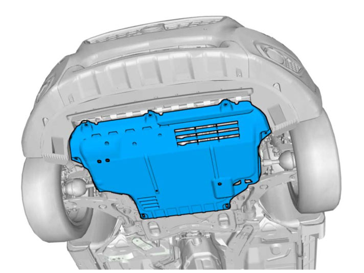
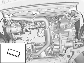
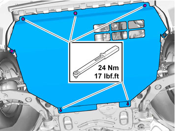
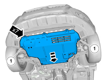
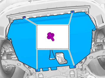
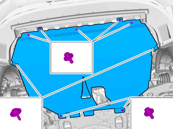
| | Applies to all models Remove the screws for the engine splash guard and remove it. The two screws (1) will be reused, place the others to one side.
|
|  | | IMG-327914 |
|
| | |
|  | | IMG-327915 |
|
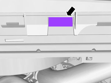
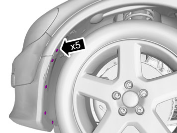
| | Applies to cars with 5-cylinder diesel engine Remove the two screws that hold the panel at the front edge of the right-hand inner wing. Remove the panel, it will not be reused, nor the rear screw. Reinstall the front screw in the inner wing.
|
|  | | IMG-327916 |
|
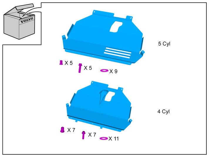
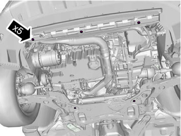
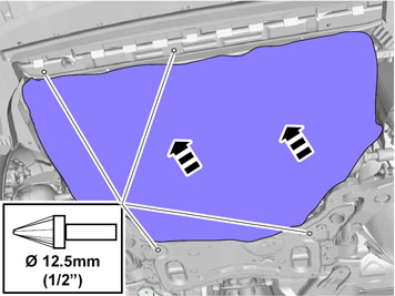
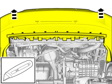
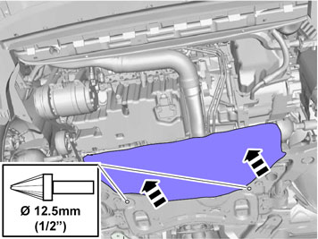
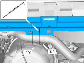
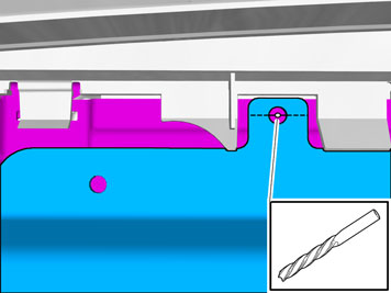
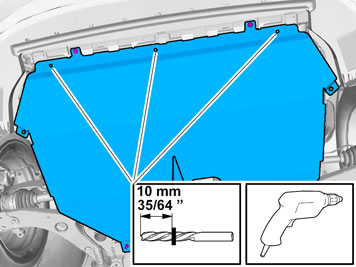
| | Applies to all cars with 5 Cyl. engines Position three thin pieces of wood, plastic or metal on the inside of the radiator bracket. One opposite the hole in the centre and one above the hole to the right. Place the third piece to the left of the left-hand hole. This is to protect components in the connection to the radiator bracket when drilling holes.
|
|  | | IMG-327917 |
|
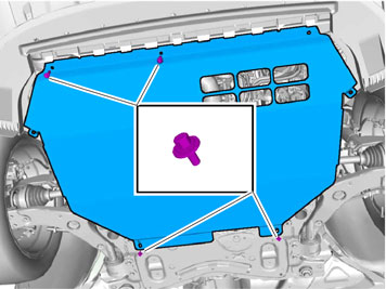
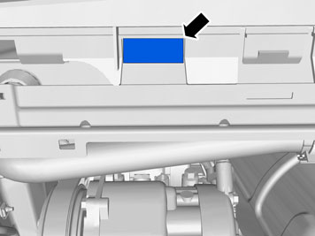
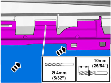
| | Cover the underneath of the engine with cardboard or similar, so that drilling swarf does not blow up into the engine compartment.
Note!
Do not drill out the front hole to the left. A new hole will be drilled to the side of it later. |
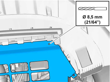
Carefully drill out the four holes where the clips were located. Use tool P/N 9814112. File down the edges of the holes. Remove any swarf.
Note!
Rustproof the hole edges thoroughly. |
Remove the cover from under the engine.
|
|  | | IMG-327928 |
|
| | |
|  | | IMG-327929 |
|
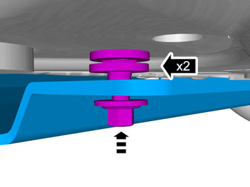
| | Install the new protective plate for marking and drilling holes for the left front mounting. At final attachment stage of the protective plate, the two screws must have two spacer washers each between the mounting lugs and the subframe. This is not required at this stage.
|
|  | | IMG-327930 |
|
| | |
|  | | IMG-327931 |
|
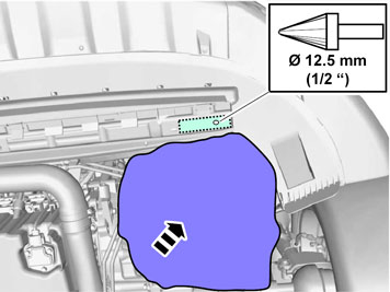
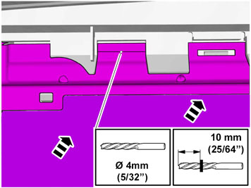
| | Cover the underneath of the engine opposite the last hole with cardboard or similar, so that drilling swarf does not blow up into the engine compartment. Carefully drill out the last hole. Use tool P/N 9814112. File down the edge of the hole. Remove any swarf.
Note!
Rustproof the hole edge thoroughly. |
Remove the cover from under the engine.
|
|  | | IMG-327932 |
|
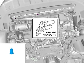
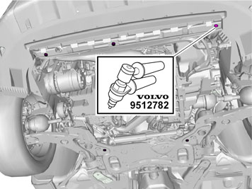
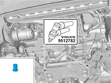
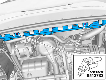
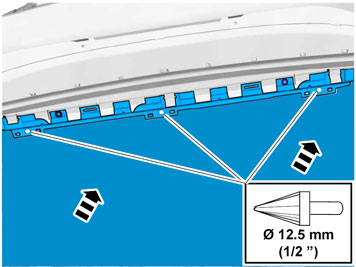
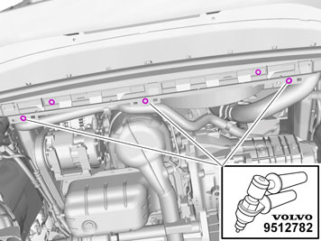
| | Rivet the nut in the drilled hole. Use tool part no. 9512782. Remove the three pieces of wood, plastic or metal from the inside of the radiator bracket.
|
|  | | IMG-327933 |
|
|  | | IMG-327934 |
|
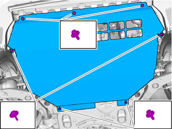
| | Illustrations A and B Note!
The two rear screws must have two spacer washers each between the mounting lug and the subframe. See image B. |
|
|  | | IMG-327935 |
|
| | |
|  | | IMG-327936 |
|
| | Applies to cars with 4 Cyl. engines Remove the screws for the engine splash guard and remove it. The two screws (1) will be reused, place the others to one side.
|
|  | | IMG-327938 |
|
| | |
|  | | IMG-327939 |
|
| | |
|  | | J8601084 |
|
|  | | J8903376 |
|
| | Illustration A Illustration B |
|  | | IMG-327943 |
|
| | Only applies to the C30 Apply a piece of tape to the panel of the wing edge to protect it. Carefully pry off the corner of the bumper cover using a weatherstrip tool until the three hooks on the inside release. Repeat the operation on the other side.
|
|  | | IMG-327944 |
|
|  | | IMG-327945 |
|
|  | | IMG-327946 |
|
| | Illustration A Pull the bumper cover at the lower edge slightly to access the locating lugs on top of the radiator. Cut off the two locating lugs where the two first holes are to be drilled. Reinstall the bumper cover.
Illustration B Illustration C |
|  | | IMG-327947 |
|
| | Cover the underneath of the engine at the rear edge with cardboard or similar, so that drilling swarf does not blow up into the engine compartment. Carefully drill out the two holes at the rear edge where the clips were located. Use tool P/N 9814112. File down the edges of the holes. Remove any swarf.
Note!
Rustproof the hole edges thoroughly. |
Remove the cover from under the engine.
|
|  | | IMG-327948 |
|
| | |
|  | | IMG-327949 |
|
| | |
|  | | IMG-327950 |
|
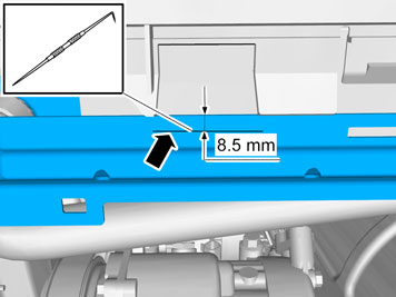
| | Make a longitudinal marking 8.5 mm (21/64 ") from the front edge and on the radiator bracket opposite where the locating lug was cut off. Do the same on the other side where the other locating lug was cut off.
|
|  | | IMG-327951 |
|
|  | | IMG-327952 |
|
| | Illustrations A and B Take workshop lift part no. 9985972 and fixture part no. 9995972 and use it as a support when handling the engine splash guard in the following points. Position the engine splash guard on the lift and raise it towards the subframe. Secure it in the two rear holes using screws and washers from the kit. One washer under the screw head and two washers between the panel and the subframe for each mounting. Do not tighten too hard as the engine splash guard must be adjusted at the front edge according to the made markings.
|
|  | | IMG-327953 |
|
|  | | IMG-327954 |
|
|  | | IMG-327955 |
|
| | Illustration A Illustrations B and C |
|  | | IMG-327964 |
|
|  | | IMG-327966 |
|
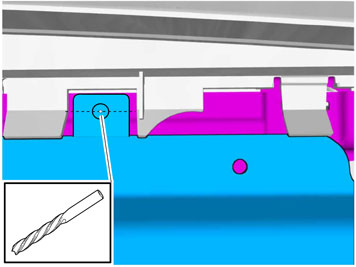
| | Illustrations A and B Note!
Use a smooth drill bit head and ensure that the drill bit does not slip off the surface to be drilled, the surface is small in relation to the completed size of the hole. |
Make a clear punch mark in the centre of the marking for both front holes. Cover part of the underneath of engine compartment to prevent swarf from being blown up. Pre-drill with a 4 mm (5/32 ") drill bit, then a 8 mm 5/16 ") drill bit and finally with drill bit part no. 9814112. Use a drill stop to prevent drilling through parts above. Remove any swarf.
Note!
Rustproof the hole edges thoroughly and as well any scriber markings. |
Remove the cover from under the engine.
|
|  | | IMG-327967 |
|
| | |
|  | | IMG-327969 |
|
| | Install the new protective plate for marking and drilling the three holes in the mounting. At final attachment stage of the protective plate, the two screws must have two spacer washers each between the mounting lugs and the subframe. This is not required at this stage.
|
|  | | IMG-327970 |
|
| | Take a drill bit with the same diameter as the three holes in the engine splash guard. Use a drill stop. Carefully drill out the three holes through the holes in the engine splash guard and radiator bracket. Remove the engine splash guard.
|
|  | | IMG-327971 |
|
| | Install the cover beneath the engine. Take drill bit part no. 9814112 and carefully drill out the three holes. File down the edges of the holes. Remove any swarf.
Note!
Rustproof the hole edges thoroughly and as well any scriber markings. |
Remove the cover from under the engine.
|
|  | | IMG-327972 |
|
| | |
|  | | IMG-327973 |
|
|  | | IMG-327974 |
|
| | Illustrations A and B Note!
The two rear screws must have two spacer washers each between the mounting lug and the subframe. See image B. |
|
|  | | IMG-327975 |
|
| | |
|  | | IMG-327976 |
|
| | |
|  | | IMG-327977 |
|
| | |
|  | | IMG-327978 |
|
| | |