| | |
| | Read through all of the instructions before starting installation. Notifications and warning texts are for your safety and to minimise the risk of something breaking during installation. Ensure that all tools stated in the instructions are available before starting installation. Certain steps in the instructions are only presented in the form of images. Explanatory text is also given for more complicated steps. In the event of any problems with the instructions or the accessory, contact your local Volvo dealer.
|
| | |
| | After installation, the car must not be washed for 48 hours When installing, the car must retain a temperature of 20 degrees C. After installation, the car must not be driven for 2 hours |
| | |
|  | | IMG-363036 |
|
| | Note!
This colour chart displays (in colour print and electronic version) the importance of the different colours used in the images of the method steps. |
Used for focused component, the component with which you will do something. Used as extra colors when you need to show or differentiate additional parts. Used for attachments that are to be removed/installed. May be screws, clips, connectors, etc. Used when the component is not fully removed from the vehicle but only hung to the side. Used for standard tools and special tools. Used as background color for vehicle components.
|
| | |
|  | | IMG-375018 |
|
| | |
|  | | IMG-372212 |
|
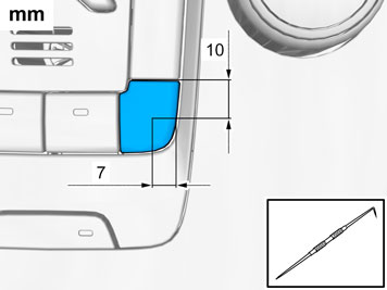
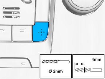
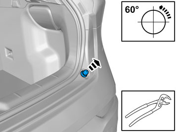
| | Measure and mark as illustrated. |
|  | | IMG-372210 |
|
| | |
|  | | IMG-372209 |
|
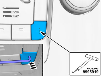
| |
Use special tool: T9995919, PULLER (SEAL-PINION,CAM-CRANKSHAFT)B200-6304
|
|  | | IMG-372207 |
|
| | |
| | |
|  | | IMG-372208 |
|
| | |
| | |
|  | | IMG-377070 |
|
| | Note!
The removal steps may contain installation details. |
|
|  | | IMG-356526 |
|
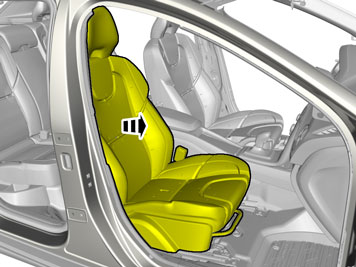
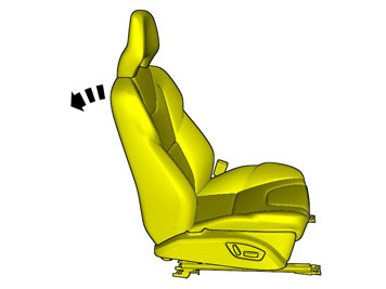
| | Adjust the seat to center position so that the seat fastening bolts can be removed. |
|  | | IMG-332193 |
|
| | Set the ignition key to position 0. |
|  | | IMG-374842 |
|
| | |
|  | | IMG-374794 |
|
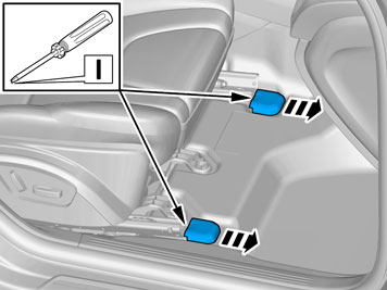
| | Repeat on the other side. |
|  | | IMG-374840 |
|
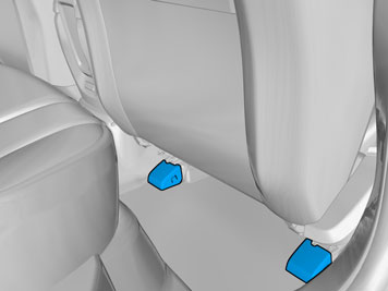
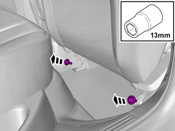
| | Remove the screws.
Tightening torque: Front seat to body
, 40 Nm
|
|  | | IMG-374795 |
|
| | |
|  | | IMG-374841 |
|
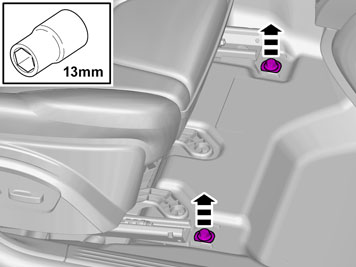
| | Remove the screws.
Tightening torque: Front seat to body
, 40 Nm
|
|  | | IMG-374838 |
|
| | |
|  | | IMG-374973 |
|
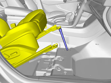
| | Place a suitable support as shown in the graphic. |
|  | | IMG-356582 |
|
| | |
|  | | IMG-366013 |
|
| | |
|  | | IMG-374839 |
|
| | |
|  | | IMG-374894 |
|
| | |
|  | | IMG-374883 |
|
| | |
|  | | IMG-375069 |
|
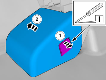
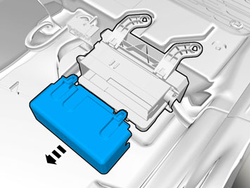
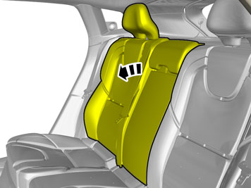
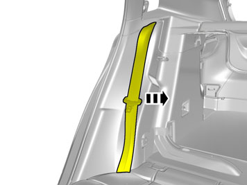
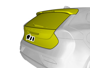
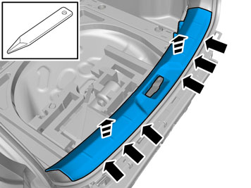
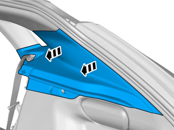
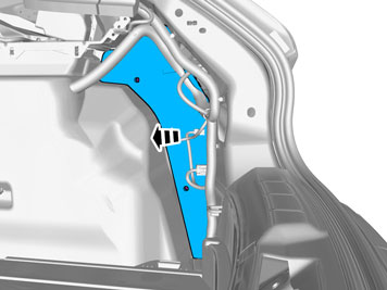
| | Release the catch. Release the lock. Remove the panel.
|
|  | | IMG-374880 |
|
| | |
|  | | IMG-374975 |
|
| | |
|  | | IMG-374881 |
|
| | |
|  | | IMG-374930 |
|
| |
Use special tool: T9512620, Stripping tool (for wiring)
|
| | |
|  | | IMG-374922 |
|
| | |
|  | | IMG-374928 |
|
| | |
|  | | IMG-374927 |
|
| |
Use special tool: T9512785, Crimping tool (included in 9512669)
|
|  | | IMG-374931 |
|
| | |
|  | | IMG-374921 |
|
| | |
|  | | IMG-374793 |
|
| | |
|  | | IMG-326808 |
|
| | Caution!
Make sure that the surrounding components are protected from heat. |
Use special tool: T9512777, Hot-air gun
|
|  | | IMG-374919 |
|
| | |
|  | | IMG-374926 |
|
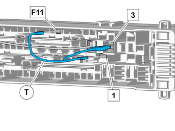
| | Connect the cable harness. |
|  | | IMG-374976 |
|
| | |
|  | | IMG-374885 |
|
| | |
|  | | IMG-374900 |
|
| | |
|  | | IMG-374855 |
|
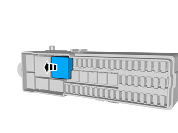
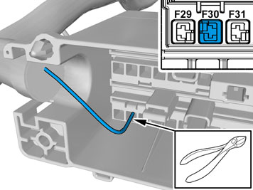
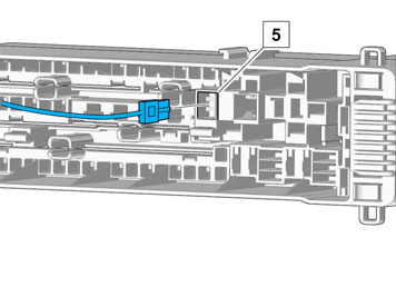
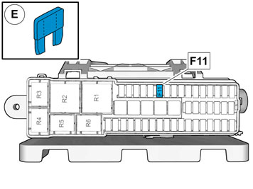
| | Find the page regarding fuses in the vehicle's manual. Copy the text in position 30 and enter this text into position 11. Cross out the text in position 30. |
| | |
| | | IMG-377070 |
|
| | Reinstall the removed parts in reverse order. |
| | |
|  | | IMG-354413 |
|
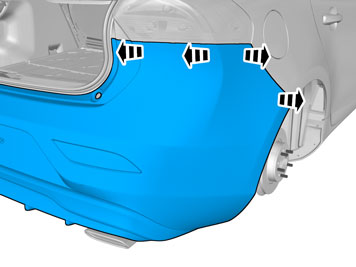
| | |
|  | | IMG-372410 |
|
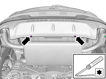
| | Repeat on the other side. |
|  | | IMG-372405 |
|
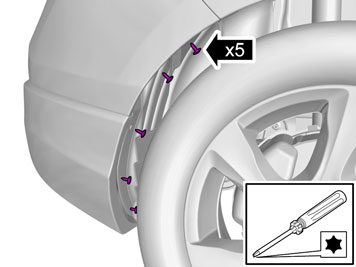
| | Remove the screws. Repeat on the other side. |
|  | | IMG-372402 |
|
| | |
|  | | IMG-357976 |
|
| | Repeat on the other side. |
|  | | IMG-355184 |
|
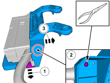
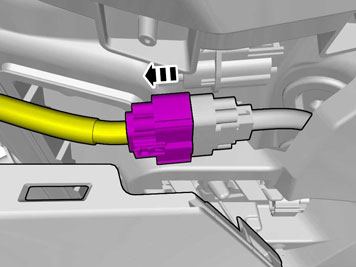
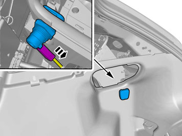
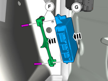
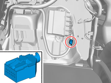
| | Release the connector's catch. Disconnect the connector. |
|  | | IMG-355166 |
|
| | |
| | |
|  | | IMG-372438 |
|
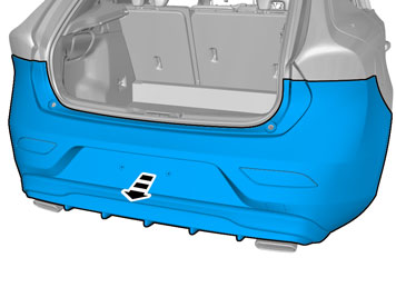
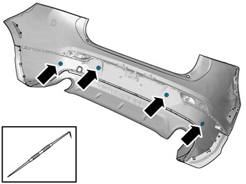
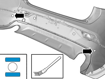
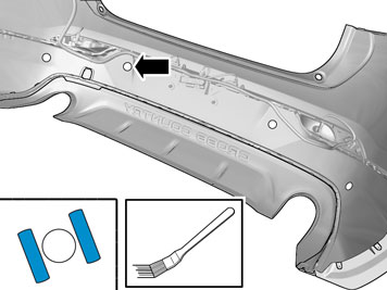
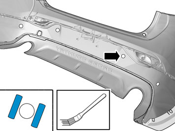
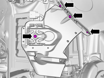
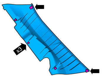
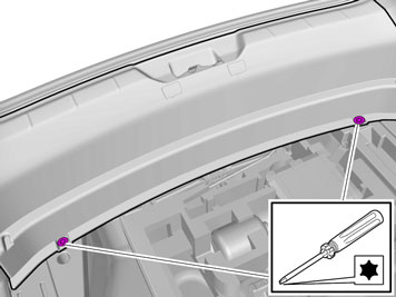
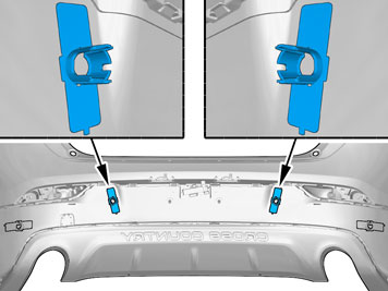
| | Locate the markings for the positions. |
|  | | IMG-372439 |
|
| | |
| 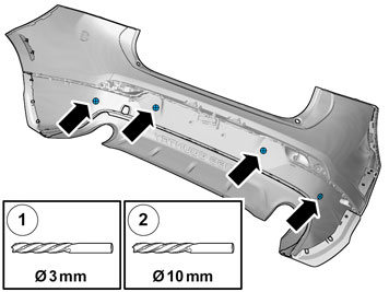 | | IMG-372441 |
|
| | |
|  | | IMG-372442 |
|
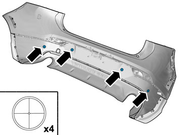
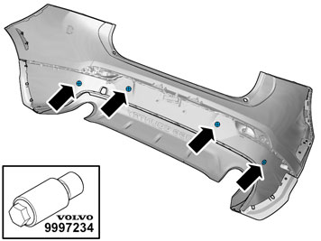
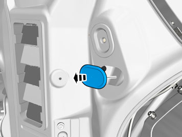
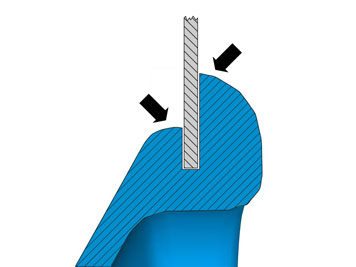
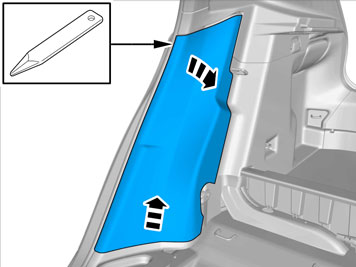
| | Caution!
Sharp end of tool must be on outside of cover. |
Use special tool: T9997234, Hole stamp
|
|  | | IMG-372443 |
|
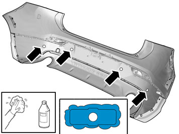
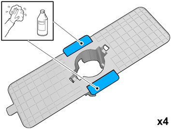
| | Clean the surfaces. Use: 1161721, Isopropanol
|
|  | | IMG-372394 |
|
| | Clean the surface. Use: 1161721, Isopropanol
|
|  | | IMG-372392 |
|
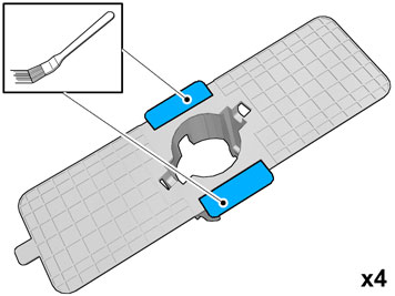
| | Apply a thin and even layer. Use: 8637076, Activator
Allow to dry for at least 10 minutes. |
|  | | IMG-372290 |
|
| | Apply a thin and even layer. Use: 8637076, Activator
Allow to dry for at least 10 minutes. |
|  | | IMG-372289 |
|
| | Apply a thin and even layer. Use: 8637076, Activator
Allow to dry for at least 10 minutes. |
|  | | IMG-372288 |
|
| | Apply a thin and even layer. Use: 8637076, Activator
Allow to dry for at least 10 minutes. |
| | |
|  | | IMG-373342 |
|
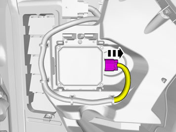
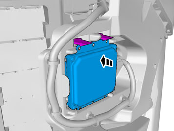
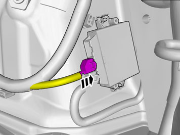
| | Disconnect the connector. |
|  | | IMG-373343 |
|
| | |
|  | | IMG-373340 |
|
| | |
|  | | IMG-372237 |
|
| | |
|  | | IMG-373346 |
|
| | |
|  | | IMG-358146 |
|
| | |
| | |
|  | | IMG-358137 |
|
| | Install component that comes with the accessory kit. |
|  | | IMG-358177 |
|
| | Caution!
Make sure that the rubber grommet seals properly to the body. |
|
| | |
|  | | IMG-373355 |
|
| | |
| | | IMG-372237 |
|
| | |
|  | | IMG-373358 |
|
| | |
| | | IMG-373343 |
|
| | |
|  | | IMG-373357 |
|
| | |
|  | | IMG-373386 |
|
| | |
| | |
|  | | IMG-355927 |
|
| | |
|  | | IMG-355932 |
|
| | |
|  | | IMG-372962 |
|
| | |
|  | | IMG-372961 |
|
| | |
|  | | IMG-368833 |
|
| | |
|  | | IMG-360944 |
|
| | Repeat on the other side. |
|  | | IMG-360951 |
|
| | |
|  | | IMG-355945 |
|
| | |
|  | | IMG-355946 |
|
| | |
|  | | IMG-356006 |
|
| | |
|  | | IMG-373665 |
|
| | |
|  | | IMG-373664 |
|
| | Disconnect the connector, if applicable. |
|  | | IMG-355942 |
|
| | |
|  | | IMG-356008 |
|
| | |
|  | | IMG-356009 |
|
| | Disconnect any connector(s). |
|  | | IMG-356007 |
|
| | |
|  | | IMG-373178 |
|
| | |
|  | | IMG-373168 |
|
| | |
|  | | IMG-358046 |
|
| | |
| | |
|  | | IMG-358053 |
|
| | |
|  | | IMG-373391 |
|
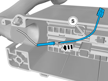
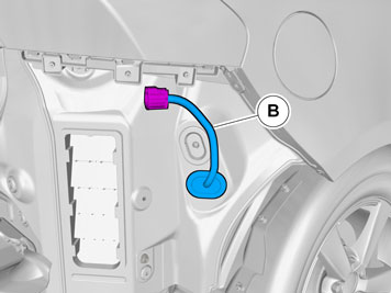
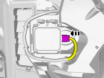
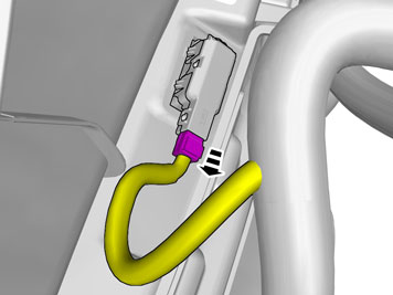
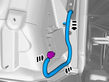
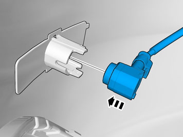
| | Pull the wiring through. Connect the connector. |
|  | | IMG-373393 |
|
| | |
|  | | IMG-372413 |
|
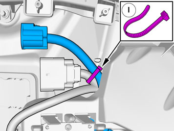
| | Locate the pre-routed connector. Remove the tape. |
|  | | IMG-372415 |
|
| | |
|  | | IMG-359181 |
|
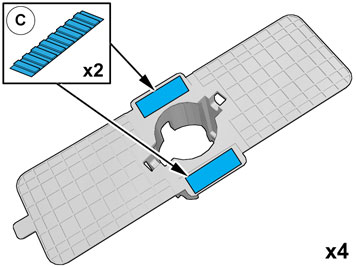
| | Note!
Prepare and install one holder at a time. |
|
|  | | IMG-372343 |
|
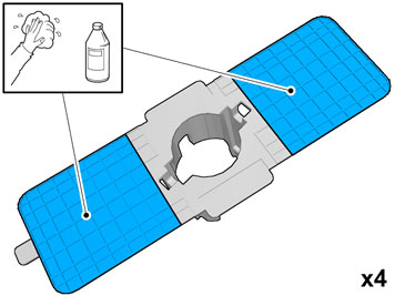
| | Remove the protective film. |
|  | | IMG-372324 |
|
| | |
|  | | IMG-372322 |
|
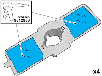
| | Warning!
Make sure to provide adequate ventilation. |
Warning!
Wear protective gloves. |
Apply a thin and even layer.
Use special tool: T9512950, Glue gun (kit)
Use: 9511027, Glue
Use: 1161730, Mixing pipe
|
|  | | IMG-372329 |
|
| | |
|  | | IMG-372328 |
|
| | |
|  | | IMG-372315 |
|
| | |
|  | | IMG-372304 |
|
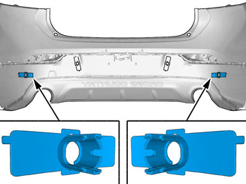
| | Note!
Apply pressure only where the tape is located. |
|
|  | | IMG-372303 |
|
| | Note!
Hold the part securely at the marker arrows when removing the tool. |
|
|  | | IMG-372351 |
|
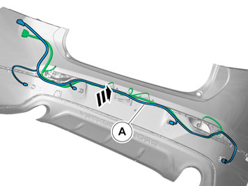
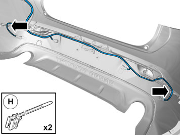
| | Put the wiring in the Bumper cover without installing the wiring. Route the cable harness to the existing cable harness. |
|  | | IMG-373743 |
|
| | |
|  | | IMG-372387 |
|
| | Repeat on the other side. |
|  | | IMG-373368 |
|
| | |
|  | | IMG-372504 |
|
| | |
|  | | IMG-373744 |
|
| | |
|  | | IMG-373387 |
|
| | |
| | |
|  | | IMG-372231 |
|
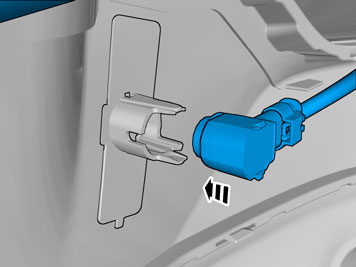
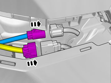
| | Place the Bumper Cover in position for installation. Connect the connectors. |
|  | | IMG-358175 |
|
| | |
| | | IMG-377070 |
|
| | Reinstall the removed parts in reverse order. |
|  | | IMG-242268 |
|
| | Download software (application) for the accessory's function according to the service information in VIDA. Order and download software according to: 31330849
|