| | |
|  | | IMG-246024 |
|
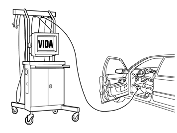
| | Applies to all models Note!
Some steps in these installation instructions are presented with illustration only. |
Work is carried out the same way on left-hand drive cars as on right-hand drive cars. Left-hand drive car shown. In cases where there are differences between left and right-hand drive cars, both versions are shown. Note!
Wait at least three minutes before unplugging the connectors or removing other electrical equipment. |
|
|  | | IMG-298585 |
|
| | |
|  | | IMG-340522 |
|
| | |
|  | | IMG-345113 |
|
| | |
|  | | IMG-339997 |
|
| | |
|  | | IMG-339998 |
|
| | |
|  | | IMG-339999 |
|
| | |
|  | | IMG-282533 |
|
| | |
|  | | IMG-340192 |
|
| | |
|  | | IMG-282544 |
|
| | |
|  | | IMG-296139 |
|
| | |
|  | | IMG-296140 |
|
| | Applies to cars with automatic transmission |
|  | | IMG-282545 |
|
| | |
|  | | IMG-340001 |
|
|  | | IMG-340196 |
|
| | Illustrations A and B Carefully pry off the centre console panel starting on both sides at the rear edge. It is secured by two clips along the long sides. On manual gearboxes, the gear lever boot is secured by four catches (1) around the gear lever panel, (Image B). Lift it up slightly and make sure that all cables are free from the gear lever carrier and components in the tunnel console, and lift it out.
|
|  | | IMG-345114 |
|
|  | | IMG-360002 |
|
|  | | IMG-360001 |
|
|  | | IMG-345115 |
|
| | Illustration A, B, C and D Use: Electrician's screwdriver |
|  | | IMG-345232 |
|
| | |
|  | | IMG-345233 |
|
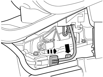
| | Carefully pull the media player out, disconnect the connectors and place them to one side. |
|  | | IMG-303385 |
|
|  | | IMG-339921 |
|
| | |
|  | | IMG-340008 |
|
| | |
|  | | IMG-340569 |
|
| | |
|  | | IMG-340508 |
|
| | |
|  | | IMG-340510 |
|
| | Take the cable harness out of the kit and place it on the left hand side of the tunnel console. Connect the 12V cable to the female connector on the cable harness and insert the remaining male connector through the hole to the position where the cup holder was located. Pull the cable forward inside the carpet for the centre console.
|
|  | | IMG-340945 |
|
| | |
|  | | IMG-340946 |
|
| | |
|  | | IMG-340665 |
|
|  | | IMG-340670 |
|
| | Illustration A Applies to left-hand drive cars Continue to route the shorter of the cables inside the centre console and up to the position for display. If necessary use a wire spring to pull the cable through. The cable is pulled forward between the air ducts. Pull the longer of the cables in front of the air ducts in the centre console over to the other side. Clamp the cable for the display into place using a cable tie and clips as illustrated in image B. Ensure that the cables are not pulled so tight that there is a risk that they can be frayed. Conceal the cable harness behind the rear edge of the carpet.
Illustration B |
|  | | IMG-340685 |
|
|  | | IMG-340693 |
|
| | Illustration A Applies to right-hand drive cars Continue to pull the shorter of the cables inside the centre console and up to the location of the display. If necessary use a wire spring to pull the cable through. Allow the longer of the cables to remain on the floor for the time being. Clamp the cable for the display into place using a cable tie and clips as illustrated in image B. Ensure that the cable is not pulled so tight that there is a risk that they can be frayed. Conceal the cable harness behind the rear edge of the carpet.
Illustration B |
|  | | IMG-340511 |
|
| | |
|  | | IMG-340130 |
|
| | |
|  | | IMG-340131 |
|
| | |
|  | | IMG-340146 |
|
| | |
|  | | IMG-303896 |
|
| | |
|  | | IMG-340147 |
|
|  | | IMG-340003 |
|
| | |
|  | | IMG-340564 |
|
| | |
|  | | IMG-340580 |
|
|  | | IMG-340554 |
|
| | |
|  | | IMG-340700 |
|
| | |
|  | | IMG-340711 |
|
| | |
|  | | IMG-340555 |
|
| | | IMG-340580 |
|
| | |
|  | | IMG-340563 |
|
| | |
|  | | IMG-340149 |
|
| | |
|  | | IMG-340150 |
|
| | |
| | | IMG-339999 |
|
| | |
|  | | IMG-339905 |
|
| | |
|  | | IMG-342716 |
|
| | |
|  | | IMG-282559 |
|
| | Applies to cars with Four-C |
|  | | IMG-340521 |
|
| | |
|  | | IMG-340523 |
|
| | |
|  | | IMG-340576 |
|
| | |
|  | | IMG-340581 |
|
| | |
|  | | IMG-340552 |
|
|  | | IMG-340547 |
|
| | |
|  | | IMG-340528 |
|
|  | | IMG-340524 |
|
|  | | IMG-340527 |
|
|  | | IMG-340525 |
|
|  | | IMG-340526 |
|
| | Image A, B, C, D and E Note!
The grille is firmly fixed so be careful with the bumper cover. |
|
|  | | IMG-340574 |
|
| | Applies to left-hand drive cars |
|  | | IMG-340567 |
|
| | |
|  | | IMG-345234 |
|
| | Applies to cars with 5-cylinder engine Carry out points 54-59 to facilitate access to the rubber grommet in the cowl panel. |
|  | | IMG-345235 |
|
| | Fold out the wing liner at the rear edge. |
|  | | IMG-345236 |
|
| | |
|  | | IMG-345397 |
|
| | |
|  | | IMG-345237 |
|
| | |
|  | | IMG-345238 |
|
| | Slide the catalytic converter to the left and secure it using a cable tie. |
|  | | IMG-340716 |
|
| | Remove the rubber lead-in in the firewall on the right hand side and place it to one side. |
|  | | IMG-340718 |
|
| | Fold back the carpets. Insert the long cable through the hole and out into the engine compartment. |
|  | | IMG-345239 |
|
| | |
|  | | IMG-340606 |
|
| | Bend the insulation panel to one side and insert the spring inside it and down to the rubber lead-in in the firewall. Tie 40 cm of a thin electric wire in the upper eyelet to allow for further extraction of the tensile spring on the underside of the car |
|  | | IMG-340721 |
|
| | |
|  | | IMG-340951 |
|
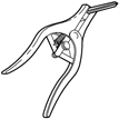
| | Take the expander expander pliers, lubricate the three expander lugs with low temperature grease. Insert the pliers and carefully expand the hole in the small rubber teat thread the rubber lead-in over the switch with cable.
Note!
Do not expand the hole more than is necessary to get the switch through, the rubber lead-in can easily split. |
|
|  | | IMG-340726 |
|
| | |
|  | | IMG-340629 |
|
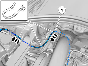
| | Place the cable where the thick cable harness goes into the cold zone (1). Route it along the cable harness around the radiator expansion tank. Clamp using tie straps around the thick cable harness. Do not tighten the clamps yet.
|
|  | | IMG-340539 |
|
| | Route the cable along the thick cable harness and cable duct forward to the headlamp location. Clamp using tie straps around the panel flange, thick cable harness and cable duct. Do not tighten the clamps yet.
|
|  | | IMG-340572 |
|
| | |
|  | | IMG-340538 |
|
|  | | IMG-340553 |
|
|  | | IMG-340578 |
|
| | Applies to cars without radiator damper Illustrations A, B and C Insert the cable through the hole in the lower edge of the front panel and out. Route the cable further on and under the right air baffle and out in front of the radiator. Press the upper spacer into place. Pull the cable through and clamp at the three panel brackets. Pull the cable after the final clamp as illustrated (Adjust the length as necessary. Leave as little excess as possible inside the grille). Do not tighten the clamps yet.
|
|  | | IMG-340733 |
|
|  | | IMG-340611 |
|
|  | | IMG-340737 |
|
| | Applies to cars with radiator damper Illustrations A, B and C Draw out the cable at the bottom under the air baffle. Push the end of the damper and air baffle to one side, and pull out the connector with cable.
|
|  | | IMG-340536 |
|
| | Place the cable under the front edge of the grille between the energy absorber and the radiator damper frame and out. Let the cable protrude approximately according to the dimensions opposite where the camera is to be located.
|
|  | | IMG-340829 |
|
| | Applies to right-hand drive cars |
|  | | IMG-340618 |
|
| | |
|  | | IMG-345240 |
|
| | Applies to cars with 4-cylinder engine Carry out points 75-76 to facilitate access to the rubber grommet in the cowl panel. Remove the screws |
|  | | IMG-345241 |
|
| | |
|  | | IMG-340542 |
|
| | Remove the rubber lead in the firewall. |
|  | | IMG-340541 |
|
| | Bend the floor mat and the insulating mat back. Insert the long cable through the hole and out into the engine compartment. |
|  | | IMG-340532 |
|
| | |
|  | | IMG-340579 |
|
| | Bend the insulation panel to one side and insert the spring inside it and down to the rubber lead-in in the firewall. Tie 40 cm of a thin electric cable in the upper eyelet to allow for further extraction of the tensile springs on the underside of the car. Note!
On cars with a 6-cylinder engine, the hoses to the heating element are inside the panel. This means that there is limited space when routing the cable. |
|
| | | IMG-340721 |
|
| | |
|  | | IMG-340954 |
|
| | Take the expander expander pliers, lubricate the three expander lugs with low temperature grease. Insert the pliers and carefully expand the hole in the small rubber teat thread the rubber lead-in over the switch with cable.
Note!
Do not expand the hole more than is necessary to get the switch through, the rubber lead-in can easily split. |
|
|  | | IMG-340738 |
|
| | |
|  | | IMG-340535 |
|
|  | | IMG-340747 |
|
| | Illustration A Pull the cable to the left inside the insulation panel and on the left hand side of the cable duct. Clamp at the cable duct. Route alongside the battery box and up to the cable at the corner of the battery box. Then tighten so that there is no risk of fraying.
Illustration B |
|  | | IMG-340751 |
|
|  | | IMG-340781 |
|
|  | | IMG-340782 |
|
| | Applies to cars without radiator damper Illustrations A, B and C Continue routing the cable from the underside of the front panel. Insert the cable out through the lead-in in the lower edge of the front panel. Route the cable on under the left air baffle and out in front of the radiator. Clamp using tie straps. Pull out the cable and clamp at the panel bracket. Pull the cable after the clamp as illustrated (Adjust the length as necessary. Leave as little excess as possible inside the grille). Do not tighten the clamps yet.
|
|  | | IMG-340565 |
|
|  | | IMG-340613 |
|
|  | | IMG-340540 |
|
| | Applies to cars with radiator damper Illustrations A, B and C Draw out the cable at the bottom under the air baffle. Push the end of the damper and air baffle to one side, and pull out the connector with cable.
|
|  | | IMG-340571 |
|
| | Place the cable under the front edge of the grille between the energy absorber and the radiator damper frame and out. Let the cable protrude approximately according to the dimensions opposite where the camera is to be located.
|
|  | | IMG-353635 |
|
| | Applies to low emission cars. (DRIV'e). Saw or cut out the hole for the camera bracket. File or grind smooth any imperfections.
|
|  | | IMG-340549 |
|
| | |
|  | | IMG-348254 |
|
| | |
|  | | IMG-348253 |
|
| | |
|  | | IMG-348252 |
|
| | Note!
Ensure to turn the camera correctly. |
|
|  | | IMG-340545 |
|
|  | | IMG-340570 |
|
|  | | IMG-340561 |
|
| | Illustration A Image B applies to left hand drive cars without radiator damper, image C with Position the grille with the left end first. Check that the cable excess is sufficient to connect the camera and press the grille into place. Connect the cable to the camera. Tighten the tie straps inside the grille (Image B).
Illustration B Illustration C |
|  | | IMG-340777 |
|
|  | | IMG-340509 |
|
|  | | IMG-340562 |
|
| | Illustration A Image B applies to right hand drive cars without radiator damper, image C with Position the grille with the left end first. Check that the cable excess is sufficient to connect the camera and press the grille into place. Connect the cable to the camera. Tighten the tie straps inside the grille (Image B).
Illustration B Illustration C |
|  | | IMG-340546 |
|
| | Applies to both left and right hand drive cars |
|  | | IMG-340544 |
|
| | Pull the excess back from the grille and insert into the passenger compartment. Tighten the clamps by hand. Press the rubber grommet into place.
|
|  | | IMG-345242 |
|
| | Applies to left-hand drive cars with 5-cylinder engine Move the catalytic converter back. |
|  | | IMG-345243 |
|
| | |
|  | | IMG-340577 |
|
| | Applies to both left and right hand drive cars Reinstall the remaining detached components in reverse order. |
|  | | IMG-336901 |
|
| | |
|  | | IMG-336904 |
|
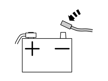
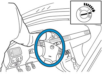
| |
Warning!
When the ignition is to be switched on for the first time after the battery has been disconnected, this must be done whilst by standing outside the vehicle, stretching your arm in and avoiding the working area for the airbags. |
|
|  | | IMG-242268 |
|
| | |