| | |
| | Read through all of the instructions before starting installation. Notifications and warning texts are for your safety and to minimise the risk of something breaking during installation. Ensure that all tools stated in the instructions are available before starting installation. Certain steps in the instructions are only presented in the form of images. Explanatory text is also given for more complicated steps. In the event of any problems with the instructions or the accessory, contact your local Volvo dealer.
|
| | |
| | These installation instructions show installation on left hand drive cars. When installing on right-hand drive cars, perform the procedures on the opposite side and/or mirrored. Where the procedure differs, the right-hand version is also shown with text and image. |
| | |
|  | | IMG-363036 |
|
| | Note!
This colour chart displays (in colour print and electronic version) the importance of the different colours used in the images of the method steps. |
Used for focused component, the component with which you will do something. Used as extra colors when you need to show or differentiate additional parts. Used for attachments that are to be removed/installed. May be screws, clips, connectors, etc. Used when the component is not fully removed from the vehicle but only hung to the side. Used for standard tools and special tools. Used as background color for vehicle components.
|
| | |
|  | | IMG-332180 |
|
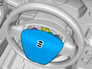
| | Warning!
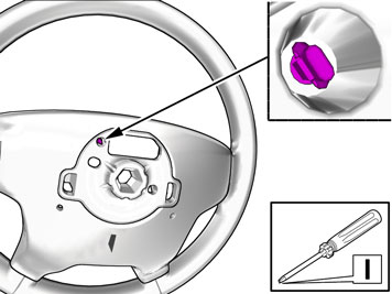
The supplemental restraint system (SRS) is active for a certain length of time after the power supply has been disconnected. Wait for a minimum of 30 seconds before disconnecting or removing any SRS components. |
Turn on the ignition. Remove the battery's negative cable.
|
| | |
|  | | IMG-378397 |
|
| | |
|  | | IMG-378605 |
|
| | |
|  | | IMG-378398 |
|
| | |
|  | | IMG-378400 |
|
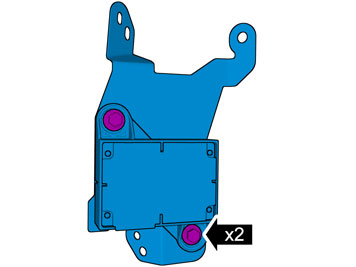
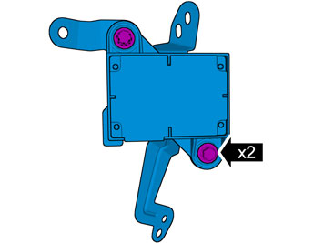
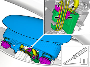
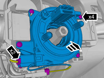
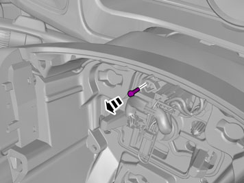
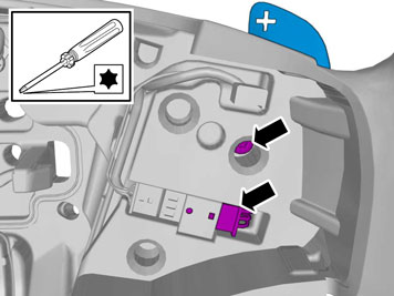
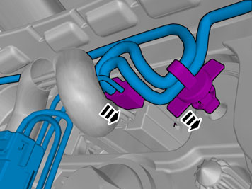
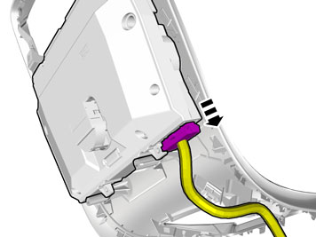
| | Install the screws. Locate the pre-routed connector. Connect the connector. |
| | Right-hand drive vehicles |
|  | | IMG-378402 |
|
| | |
|  | | IMG-378626 |
|
| | |
|  | | IMG-378403 |
|
| | |
|  | | IMG-378404 |
|
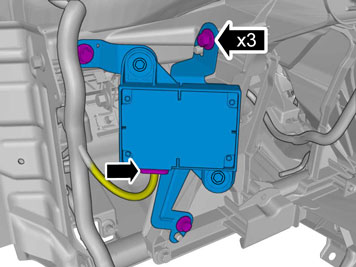
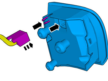
| | Install the screws. Locate the pre-routed connector. Connect the connector. |
| | |
|  | | IMG-345551 |
|
| | |
|  | | IMG-345553 |
|
| | |
|  | | IMG-344722 |
|
| | |
|  | | IMG-345554 |
|
| | |
|  | | IMG-345555 |
|
| | |
|  | | IMG-337683 |
|
| | |
|  | | IMG-344725 |
|
| | |
|  | | IMG-344726 |
|
| | |
|  | | IMG-344727 |
|
| | |
|  | | IMG-345556 |
|
| | |
|  | | IMG-349359 |
|
| | Repeat on the other side. |
|  | | IMG-345558 |
|
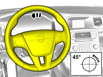
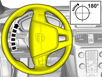
| | Repeat the steps when removing on opposite side. Turn the steering wheel into neutral position. |
|  | | IMG-344730 |
|
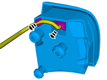
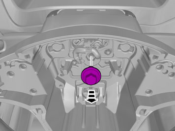
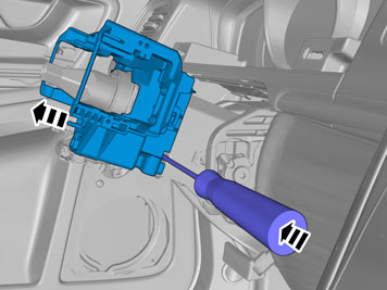
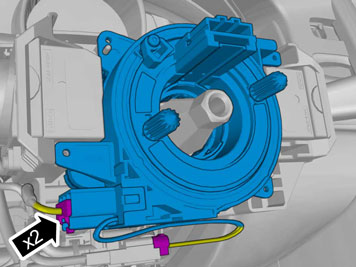
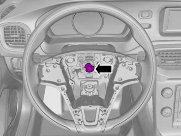
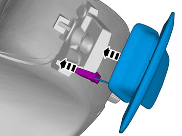
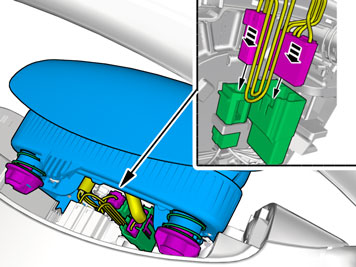
| | Release the connector's catch. Disconnect the connectors. |
|  | | IMG-344731 |
|
| | |
| | Warning!
Place the airbag module with the front side facing up in a safe storage area during work. |
|
|  | | IMG-345559 |
|
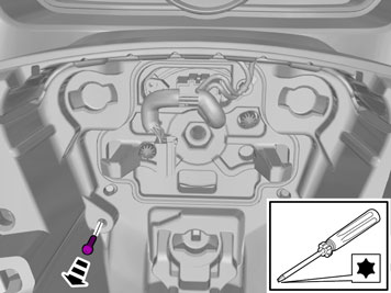
| | Note!
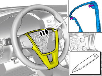
This step requires considerable force. |
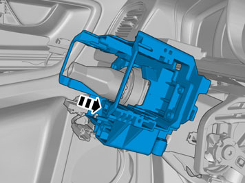
Detach the panel. |
|  | | IMG-345560 |
|
| | Note!
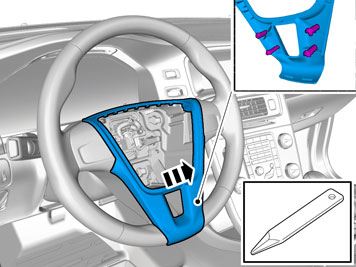
This step requires considerable force. |
Remove the panel. |
|  | | IMG-373323 |
|
| | Note!
This step requires considerable force. |
Repeat on the other side. |
|  | | IMG-373322 |
|
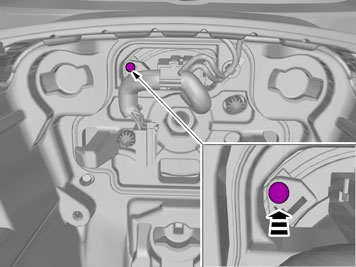
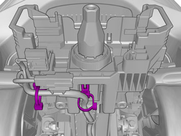
| | Disconnect the connector. |
|  | | IMG-344121 |
|
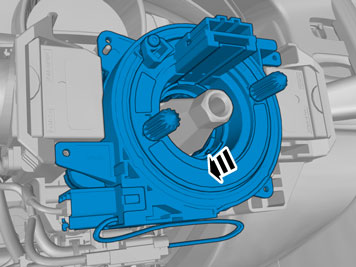
| | Disconnect the connector. Repeat on the other side. |
|  | | IMG-373344 |
|
| | |
|  | | IMG-373345 |
|
| | |
|  | | IMG-373339 |
|
| | |
|  | | IMG-373341 |
|
| | Reinstall the screw. Use hands only. |
|  | | IMG-373348 |
|
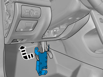
| | Remove the part carefully |
|  | | IMG-344511 |
|
| | Remove the cable harness clips. |
|  | | IMG-373349 |
|
| | |
|  | | IMG-378827 |
|
| | |
|  | | IMG-378828 |
|
| | |
|  | | IMG-378829 |
|
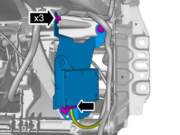
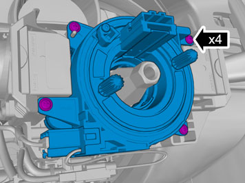
| | Remove the screws. Disconnect the connectors. |
|  | | IMG-378830 |
|
| | Remove the screws. Repeat on the other side. |
|  | | IMG-378831 |
|
| | |
|  | | IMG-378855 |
|
| | |
|  | | IMG-378832 |
|
| | |
| | |
|  | | IMG-378854 |
|
| | |
| | | IMG-378855 |
|
| | |
|  | | IMG-378856 |
|
| | |
|  | | IMG-378878 |
|
| | |
|  | | IMG-378852 |
|
| | |
|  | | IMG-378853 |
|
| | |
| | |
|  | | IMG-377070 |
|
| | Reinstall the removed parts in reverse order. |
| | |
|  | | IMG-373366 |
|
| | |
|  | | IMG-373383 |
|
| | |
|  | | IMG-373392 |
|
| | |
|  | | IMG-373394 |
|
| | |
|  | | IMG-373623 |
|
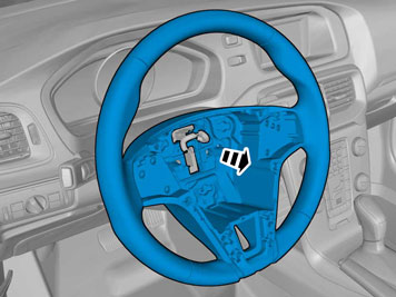
| |
Tightening torque: Steering wheel to steering column (center screw)
, 48 Nm
|
|  | | IMG-378459 |
|
| | |
|  | | IMG-378449 |
|
| | Repeat on the other side. |
|  | | IMG-378450 |
|
| | Repeat on the other side. |
|  | | IMG-344510 |
|
| | Repeat on the other side. |
|  | | IMG-373385 |
|
| | |
|  | | IMG-373389 |
|
| | Connect the connector. Install the clip(s). |
|  | | IMG-373390 |
|
| | |
|  | | IMG-373388 |
|
| | |
|  | | IMG-344748 |
|
| | |
| | |
|  | | IMG-349387 |
|
| | Caution!
Make sure that no part of the wiring harness is trapped. |
Reinstall the removed parts in reverse order. |
| | |
|  | | IMG-292804 |
|
| | |
|  | | IMG-292806 |
|
| | |
|  | | IMG-292823 |
|
| | Unhook the cable harness clips. Disconnect the connector. |
|  | | IMG-292826 |
|
| | |
|  | | IMG-292827 |
|
| | Disconnect the connector, if applicable. |
|  | | IMG-346236 |
|
| | |
|  | | IMG-340984 |
|
| | Disconnect the connector. |
|  | | IMG-340985 |
|
| | |
|  | | IMG-355818 |
|
| | |
| | Cars with automatic transmissions |
|  | | IMG-293006 |
|
| | |
|  | | IMG-293007 |
|
| | Release the shift-lock function. |
|  | | IMG-340981 |
|
| | |
|  | | IMG-340604 |
|
| | |
|  | | IMG-340605 |
|
| | |
|  | | IMG-340607 |
|
| | |
|  | | IMG-381763 |
|
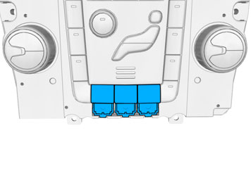
| | Select the first free position closest to the driver. |
|  | | IMG-382076 |
|
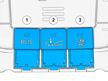
| | If all locations for the switch are occupied a switch with function must be removed in priority order as illustrated. |
|  | | IMG-380450 |
|
| | |
| | |
|  | | IMG-382543 |
|
| | |
| | |
|  | | IMG-336901 |
|
| | Reinstall the removed parts in reverse order. Reinstall the battery's negative cable. |
|  | | IMG-336904 |
|
| | Warning!
When switching the ignition on for the first time after a battery disconnect and connect, make sure to stand outside the vehicle and only reach into the vehicle keeping clear of the air bag deployment areas. |
|
|  | | IMG-275777 |
|
| | |
|  | | IMG-242268 |
|
| | Download software (application) for the accessory's function according to the service information in VIDA. Order and download software according to: 31275377
|
| | | IMG-275777 |
|
| | |
| | | IMG-242268 |
|
| | Download software (application) for the accessory's function according to the service information in VIDA. Order and download software according to: 31373842
|