| | |
|  | | IMG-352652 |
|
| | |
|  | | IMG-352653 |
|
| | |
|  | | IMG-352654 |
|
| | |
| | | IMG-352653 |
|
| | |
|  | | IMG-352655 |
|
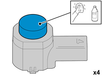
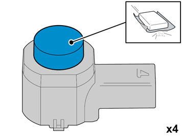
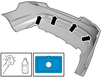
| | Caution!
Protect the connections' contact surfaces against paint. |
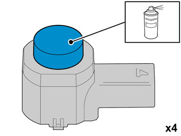
Paint the sensors in the same colour code as the vehicle. Use Volvo Touch-up paint (Only use base coat.) Use: Volvo 2-K Varnish. P/N: 31335447.
Note!
Also read the instructions on the spray can. |
|
|  | | IMG-352658 |
|
| | Caution!
The paint must have dried after the first application. |
|
|  | | IMG-334508 |
|
| | |
|  | | IMG-334509 |
|
| | |
|  | | IMG-334510 |
|
| | |
|  | | IMG-334511 |
|
| | |
|  | | IMG-334512 |
|
| | |
|  | | IMG-334513 |
|
| | |
|  | | IMG-334514 |
|
| | |
|  | | IMG-334515 |
|
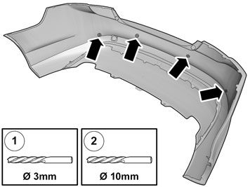
| | Ø 3 mm (7/64 ") Ø 10 mm (25/64 ")
|
|  | | IMG-334516 |
|
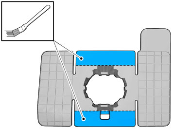
| | Note!
The hole tool's support sleeve must be on the inside, and the cutting part on the outside of the bumper casing. |
|
|  | | IMG-334517 |
|
| | |
|  | | IMG-334518 |
|
| | |
|  | | IMG-334519 |
|
| | |
|  | | IMG-334523 |
|
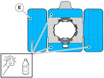
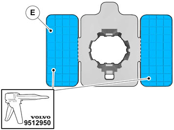
| | Apply a thin layer and even layer of activator. Allow to dry for at least 10 minutes. Use: 8637076 - Activator.
|
|  | | IMG-334524 |
|
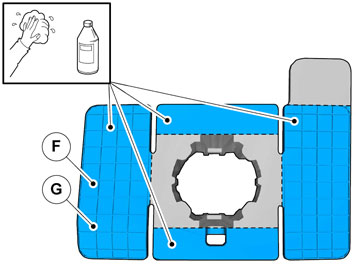
| | Apply a thin layer and even layer of activator. Allow to dry for at least 10 minutes. Use: 8637076 - Activator.
|
|  | | IMG-334525 |
|
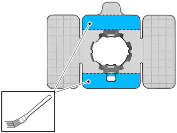
| | Apply a thin layer and even layer of activator. Allow to dry for at least 10 minutes. Use: 8637076 - Activator.
|
|  | | IMG-334528 |
|
| | |
|  | | IMG-242961 |
|
| | |
|  | | IMG-242962 |
|
| | |
|  | | IMG-242963 |
|
| | |
|  | | IMG-334529 |
|
| | |
|  | | IMG-242964 |
|
| | |
|  | | IMG-226483 |
|
| | |
|  | | IMG-334530 |
|
| | |
|  | | IMG-334531 |
|
| | |
|  | | IMG-334532 |
|
| | |
|  | | IMG-334533 |
|
| | |
|  | | IMG-334534 |
|
| | |
|  | | IMG-242966 |
|
| | |
|  | | IMG-334535 |
|
| | Applies to cars with emergency opening handle in the cargo compartment |
|  | | IMG-334536 |
|
| | |
|  | | IMG-334537 |
|
| | |
|  | | IMG-334538 |
|
| | |
|  | | IMG-334539 |
|
| | |
|  | | IMG-334540 |
|
| | |
|  | | IMG-242968 |
|
| | Remove the load divider lock by using a weatherstrip tool to pry between the carpet and lock. If performing the operation on the left side, unplug the connector.
|
|  | | IMG-221974 |
|
| | |
|  | | IMG-242969 |
|
| | |
|  | | IMG-242970 |
|
| | Mark out the stop braces for the roof in relation to the screws and nuts on the right side. Remove the screw, nut and the roof's stop braces.
|
|  | | IMG-221976 |
|
| | |
|  | | IMG-221978 |
|
| | |
|  | | IMG-229640 |
|
| | Applies to cars with keyless locking systems |
|  | | IMG-334541 |
|
| | Applies to cars with keyless locking systems |
|  | | IMG-334542 |
|
| | Applies to cars with keyless locking systems |
|  | | IMG-334543 |
|
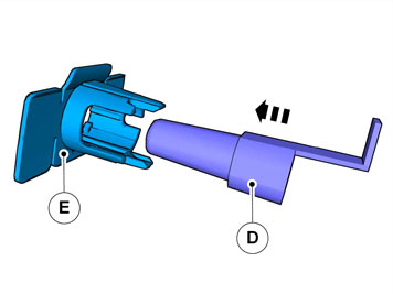
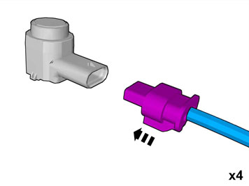
| | Applies to cars with keyless locking systems Remove the Keyless system aerial by pushing it up. Remove the connector on the antenna by pulling out the red catch and pressing in the other catch. Remove the cable harness. It shall not be re-used.
|
|  | | IMG-334544 |
|
| | Applies to cars without keyless locking systems |
|  | | IMG-334545 |
|
| | |
|  | | IMG-334546 |
|
| | Applies to cars with keyless systems Connect and reinstall the aerial.
Applies to cars without keyless systems Secure the loose connector using butyl tape to prevent rattling.
|
|  | | IMG-334547 |
|
| | |
|  | | IMG-334548 |
|
| | |
|  | | IMG-334549 |
|
| | |
|  | | IMG-334550 |
|
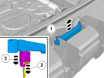
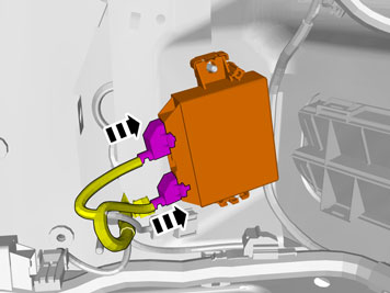
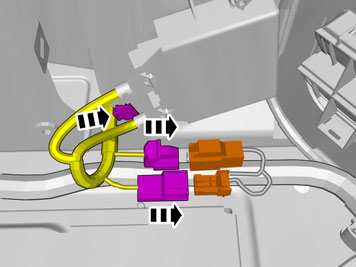
| | Connect the green 5-pin connector to the green connector that is taped to the car's usual cable harness. Connect the grey 2-pin connector to the corresponding grey connector. Secure the clip of the cable harness to the panel edge.
|
|  | | IMG-334551 |
|
| | Applies to cars with a trailer module (TRM) The car's usual green connector is connected to the TRM. Disconnect this connector. Connect the removed connector to the taped connector on the cable harness for PAM. Connect the other connector from the cable harness for PAM to the TRM.
Note!
It is important that the Parking Assistance Module (PAM) is connected as the first module and that the cable harnesses are connected correctly, and not in a loop. |
|
|  | | IMG-223844 |
|
| | Applies to cars with an accessory electronic module (AEM) The car's usual green connector is connected to the cable harness for the AEM. Disconnect this connector. Connect the removed connector to the taped connector on the cable harness for PAM. Connect the other connector from the cable harness for PAM to the cable harness for AEM.
Note!
It is important that the Parking Assistance Module (PAM) is connected as the first module and that the cable harnesses are connected correctly, and not in a loop. |
|
|  | | IMG-334552 |
|
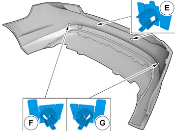
| | Note!
Prepare and install one cradle at a time. |
|
|  | | IMG-334553 |
|
| | |
|  | | IMG-334554 |
|
| | |
|  | | IMG-334555 |
|
| | |
|  | | IMG-334556 |
|
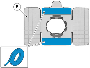
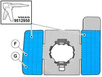
| | Apply a thin layer and even layer of adhesive. Use special tool: 9512767 - Adhesive gun Use: 116173 - Mixing pipe and 9511027 - Adhesive.
Caution!
The adhesive must not come into contact with the tape. |
|
|  | | IMG-334557 |
|
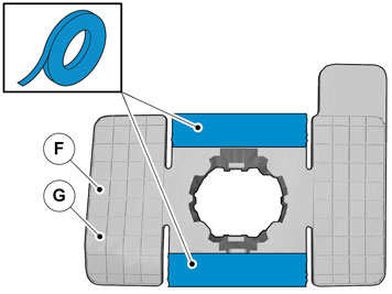
| | Apply a thin layer and even layer of adhesive. Use special tool: 9512767 - Adhesive gun. Use: 116173 - mixing pipe and 9511027 - Adhesive.
Caution!
The adhesive must not come into contact with the tape. |
|
|  | | IMG-334558 |
|
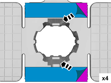
| | Note!
Note the position of the cradles. |
|
|  | | IMG-297571 |
|
| | |
|  | | IMG-297572 |
|
| | |
|  | | IMG-297573 |
|
| | |
|  | | IMG-334559 |
|
| | |
|  | | IMG-333972 |
|
| | |
|  | | IMG-333973 |
|
| | |
|  | | IMG-334560 |
|
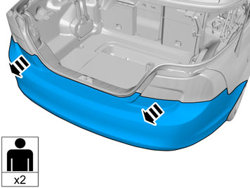
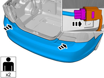
| | Position the bumper so that the bumper wiring can be connected. Reinstall the bumper Reinstall the detached components in reverse order. Load securing eyelets tightening torque: 24 Nm (17 lbf.ft).
Hint
It is easier to install the bumper if two persons help each other. |
|
|  | | IMG-242268 |
|
| | |