2012 L.H.D

Installation Instruction

Installation instructions, accessories
Volvo Car Corporation Gothenburg, Sweden
XC90 2012
XC90 (03-) 2012 L.H.D

Instruction NoVersionPart. No.Click to download PDF-version of this Installation Instruction
313395891.231339587
Running board


IMG-229762


Equipment
IMG-345497
IMG-239664
IMG-333293
IMG-332313

IMG-352774


INTRODUCTION

  • Read through all of the instructions before starting installation.

  • Notifications and warning texts are for your safety and to minimise the risk of something breaking during installation.

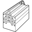
  • Ensure that all tools stated in the instructions are available before starting installation.

  • Certain steps in the instructions are only presented in the form of images. Explanatory text is also given for more complicated steps.

  • In the event of any problems with the instructions or the accessory, contact your local Volvo dealer.

 
1
R8101617
 

  • Wash clean under the door sills, in front of the rear wheels and behind the front wheels, on the right and left-hand sides.

  • Raise the car.


    Note!

    Ensure that the lifting tool does not block the location where the Running board is to be attached.


  • Remove the two M10 screws from the front bottom flange and the two M12 screws at the rear, on the right and left-hand sides. Place the screws to one side, they will not be reused.

  • Clean the mating surfaces, where the Running board is to be attached, from dirt and any underseal.

2
IMG-352775
 

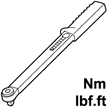
  • Take an aluminium profile, one mounting for each, four M8 screws and washers from the kit. Install the mountings in the aluminium profile as illustrated and screw in the four M8 screws. Check that there is no play between the aluminium profile and the mounting brackets at (A). Torque tighten the M8 screws to 25 Nm (19 lbf. ft).

  • Perform the same for the other aluminium profile.

3
R8101618


Hint

It is recommended that two people help when installing the Running board.


  • Install the Running board with the M10 (1) and M12 (2) screws with relevant washers.

4
R8101807
 

  • Tighten the M10 (1) screws to 50 Nm (37.5 lbf. ft) and the M12 (2) to 80 Nm (60 lbf. ft).


Running board, Foot step


Note!

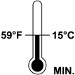
During installation the underlying surface must be kept at a temperature of at least +15°C (59°F).

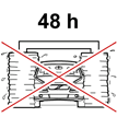
Do not wash the car within 48 hours after installation is completed.

Allow the car to remain inside for at least two hours after installation is completed if outside temperature is less than +15°C (59°F).


5
IMG-229765
 

  • Wash the "Running board" clean on the top and along the sides.

  • Wipe dry.

6
IMG-229766
 

  • Measure 170 mm (6 11/16") from the front joint between the "Running board" profile and the mounting as illustrated.

  • Mark with pencil.

7
IMG-229767
 

  • Measure 70 mm (2 3/4") from the rear joint between the "Running board" profile and the mounting as illustrated.

  • Mark with pencil.

8
IMG-229768
 

  • Align the foot steps to the "Running board" with the outer edge at the pencil markings and in toward the centre of the "Running board" as illustrated.

  • Check that the foot step is correctly aligned and draw around it with a whiteboard pen.

9
IMG-229772
 

  • Remove the protective film from the three strips of tape.

10
IMG-229773
 

  • Hold the foot step slightly above the "Running board", inside the markings drawn. Align the foot step in relation to the "Running board" and check that the cut-outs in the foot step are opposite the raised areas in the "Running board".

  • Lower the foot step and press it firmly into the "Running board".


    Note!

    Take care with the fit as the tape on the underside of the foot step adheres immediately on contact with the surface.


  • Repeat the above for both sides and for all foot steps.

  • Wash away the markings.