| | |
|  | | IMG-352652 |
|
| | |
|  | | IMG-352653 |
|
| | |
|  | | IMG-352654 |
|
| | |
| | | IMG-352653 |
|
| | |
|  | | IMG-352655 |
|
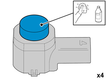
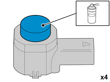
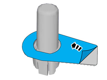
| | Caution!
Protect the connections' contact surfaces against paint. |
Paint the sensors in the same colour code as the vehicle. Use Volvo Touch-up paint (Only use base coat.) Use Volvo 2-K Varnish. P/N: 31335447.
Note!
Also read the instructions on the spray can. |
|
|  | | IMG-352658 |
|
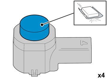
| | Caution!
Ensure that the paint has dried after painting. |
|
|  | | IMG-334681 |
|
| | |
|  | | IMG-334872 |
|
| | Applies to cars with headlamp washing |
|  | | IMG-334683 |
|
| | Applies to cars with headlamp washing Caution!
do not damage painted surfaces and high pressure washer nozzles. |
|
|  | | IMG-334684 |
|
| | |
|  | | IMG-334874 |
|
| | |
|  | | IMG-334875 |
|
| | |
|  | | IMG-334876 |
|
| | Hint
Removal of the bumper is facilitated if carried out by 2 people. |
|
|  | | IMG-334688 |
|
| | Applies to cars with fog lamps |
|  | | IMG-334959 |
|
| | |
|  | | IMG-334960 |
|
| | |
|  | | IMG-334961 |
|
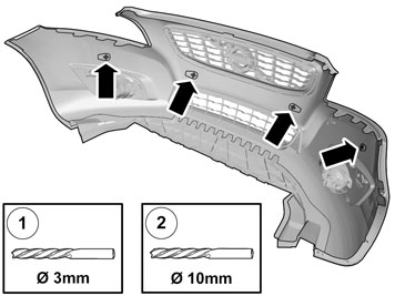
| | Ø 3 mm /7/64 ") Ø 10 mm (25/64 ")
|
|  | | IMG-334962 |
|
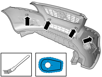
| | Note!
The hole tool's support sleeve must be on the inside, and the cutting part on the outside of the bumper casing. |
|
|  | | IMG-334963 |
|
| | Use: Isopropanol Allow to dry.
|
|  | | IMG-334965 |
|
| | Caution!
Allow to dry for at least 10 minutes. |
|
|  | | IMG-334696 |
|
| | Use: Isopropanol Allow to dry.
|
|  | | IMG-334697 |
|
| | Use: 8637076 Activator. Apply a thin layer.
Caution!
Allow to dry for at least 10 minutes. |
|
|  | | IMG-334966 |
|
| | |
|  | | IMG-335003 |
|
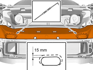
| | Note!
There are two types of member (energy absorbing). |
Foam member (EPS): Remove the foam member from the collision member. Saw along the 2 markings. Reinstall the foam member.
|
|  | | IMG-240082 |
|
| | |
|  | | IMG-253723 |
|
| | |
|  | | IMG-230429 |
|
| | |
|  | | IMG-335004 |
|
| | |
|  | | IMG-263944 |
|
| | |
|  | | IMG-263945 |
|
| | |
|  | | IMG-230432 |
|
| | |
|  | | IMG-221661 |
|
| | Steps 58-82 apply to cars with external amplifier. |
|  | | IMG-242961 |
|
| | |
|  | | IMG-242962 |
|
| | |
|  | | IMG-242963 |
|
| | |
|  | | IMG-226480 |
|
| | |
|  | | IMG-242964 |
|
| | |
|  | | IMG-226483 |
|
| | |
|  | | IMG-221942 |
|
| | |
|  | | IMG-221960 |
|
| | |
|  | | IMG-221961 |
|
| | Applies to cars with a tool box Take the tools out of the toolbox.
Remove: the screw clip the screw the toolbox.
|
|  | | IMG-221962 |
|
| | |
|  | | IMG-242965 |
|
| | Remove the cover for the tailgate's stop, by prying, with a weatherstrip tool, between the cover and the sealing strip. Carry this out on both the left and right-hand sides.
|
|  | | IMG-242966 |
|
| | |
|  | | IMG-242967 |
|
| | Applies to cars with emergency opening handle in the cargo compartment |
|  | | IMG-221966 |
|
| | |
|  | | IMG-221967 |
|
| | |
|  | | IMG-221968 |
|
| | |
|  | | IMG-221969 |
|
| | Steps 75-82 apply to both right and left-hand drive cars. On right-hand drive cars, the procedure only needs to be carried out on the left-hand side in the cargo compartment. |
|  | | IMG-221972 |
|
| | Mark out the stop bracket for the roof in relation to the screw. Remove the screw and the roof's stop bracket. Carry out on both the left and right-hand sides.
|
|  | | IMG-242968 |
|
| | |
|  | | IMG-221974 |
|
| | |
|  | | IMG-242969 |
|
| | |
|  | | IMG-242970 |
|
| | Mark out the stop brackets for the roof in relation to the screw and the nut. Remove the screw, nut and the roof's stop braces. Carry out on both the left and right-hand sides.
|
|  | | IMG-221976 |
|
| | |
|  | | IMG-221978 |
|
| | |
|  | | J3703545 |
|
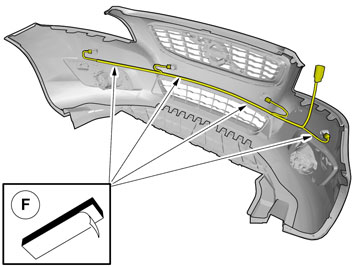
| | Note!
Ensure that the cable harness does not lie against any moving components or too close to heat sources. |
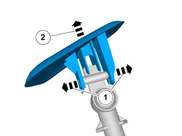
Take the short cable harness from the kit. Remove the taped connector from the cable harness. Pull the end with the loose terminals in under the headlamp Continue to pull the cable harness (1) along the right-hand side of the car, under the expansion tank down to the cowl panel. Route the cable so that it is concealed and cannot be damaged or worn. Secure the cable harness using tie straps so that it does not move.
|
|  | | J8504868 |
|
| | Unscrew the clips holding the floor carpet. Fold aside the floor mat to access the bulkhead panel inside. Take care not to create folds in the carpet.
|
|  | | IMG-253760 |
|
| | Locate the hole for the rubber grommet under the insulation panel. Make a small cut in the insulation panel starting just above the hole, continue to the center of the hole and then straight down.
|
|  | | IMG-253761 |
|
| | |
|  | | IMG-253762 |
|
| | Note!
Applies to cars with fuel powered parking heaters. Protect the coolant hose on the horizontal connection of the water pump when making the markings for holes. |
|
|  | | IMG-229750 |
|
| | |
|  | | IMG-235950 |
|
| | Take the rubber grommet from the kit and cut the top off the smaller rubber nipples Lubricate the rubber grommet. Use low temperature grease (P/N 1161417). Thread the rubber grommet onto the cable harness. Route the cable harness through the hole and press in the rubber grommet in the hole so that it seals properly. Pull the cable harness so that the correct length remains in the engine compartment. Make sure that the cable harness heating hose is in contact against the rubber grommet and secure it with a cable tie.
|
|  | | J3703487 |
|
| | Blue (BL) Green (GN) Violet (VO) Yellow (Y) White (W) Black (SB)
|
|  | | J8505029 |
|
| | Take the long cable harness from the kit. Connect it to the connector. Route the cable harness from the lower edge of the A pillar and further back at the sill and under the carpet. Fold back the carpet and screw the clip into place.
|
|  | | IMG-335009 |
|
| | |
|  | | IMG-230444 |
|
| | Applies to left-hand drive cars |
|  | | IMG-335011 |
|
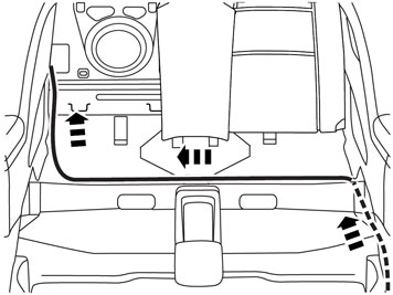
| | Applies to right-hand drive cars Route the cable over to the right-hand side of the car and further back along the existing cable harness backwards and into the cargo compartment. Position the cable so that is does not get trapped or damaged.
|
|  | | IMG-335012 |
|
| | |
|  | | IMG-335013 |
|
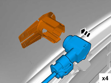
| | Note!
Make sure that the connector clicks into place and is properly secured. |
|
|  | | IMG-334742 |
|
| | |
|  | | IMG-334743 |
|
| | |
|  | | IMG-334744 |
|
| | |
|  | | IMG-335020 |
|
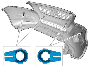
| | Note!
The cradles must be installed facing in the direction as shown in the figure. |
|
|  | | IMG-335021 |
|
| | Note!
The large grey connector must be on the right side of the bumper cover. On right-hand drive cars it must be on the left. |
|
|  | | IMG-334746 |
|
| | |
|  | | IMG-334747 |
|
| | |
|  | | IMG-334748 |
|
| | |
|  | | IMG-335022 |
|
| | |
|  | | IMG-227987 |
|
| | Hold the bumper up against the car and connect the connector for the sensor cable to the connector at the car. Secure the assembled connector on the member (1). Use a tie strap on each side of the connector Connect the connectors to the fog lamps, if installed. Slide the bumper cover into the correct position
|
|  | | IMG-335026 |
|
| | Guide the lower edge of the bumper cover into the guides Reinstall the bumper cover. Reinstall the engine splash guard. Reinstall the detached components in reverse order. Load securing eyelets, tightening torque: 24 Nm (17 lbf.ft.).
|
|  | | IMG-242268 |
|
| | |