2012 L.H.D

Installation Instructions

Installation instructions, accessories
Volvo Car Corporation Gothenburg, Sweden
S40 2012
S40 (04-) 2012

Instruction NoVersionPart. No.Click to download PDF-version of this Installation Instruction
313165161.430782183, 31399075, 30786585, 31269429
Parking assistance, button


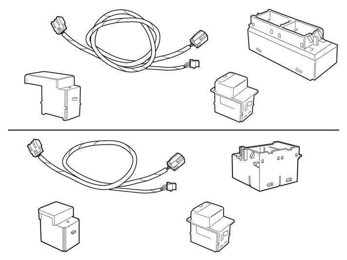
Equipment
IMG-242205
IMG-345497

IMG-373418


INTRODUCTION

  • Read through all of the instructions before starting installation.

  • Notifications and warning texts are for your safety and to minimise the risk of something breaking during installation.

  • Ensure that all tools stated in the instructions are available before starting installation.

  • Certain steps in the instructions are only presented in the form of images. Explanatory text is also given for more complicated steps.

  • In the event of any problems with the instructions or the accessory, contact your local Volvo dealer.

 
1
IMG-332193
 

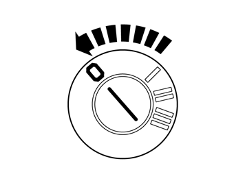
  • Set the ignition key to position 0.


Note!

Wait at least one minute before unplugging the connectors or removing other electrical equipment


2
J8504532
 

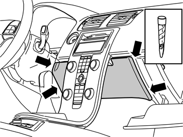
  • Remove the panel inside the center console. It is secured by four hidden clips.

3
J8504893
 

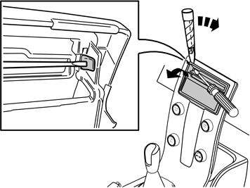
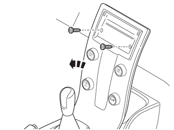
  • Remove the surround from around the display and media player. Use a small screwdriver and press in the catch in one of the surround's upper corners. Carefully bend loose the surround on the same side with a plastic weatherstrip tool.


    Note!

    Do not damage the panel and dashboard.


  • Do the same on the other side.


    Hint

    If the panel is difficult to remove, press the panel on both sides again and repeat the procedure starting at the other side.


  • Fold the surround backwards. Remove by pulling upwards.

4
J8504534
 

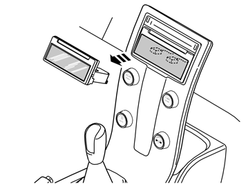
  • Remove the infotainment control module (ICM). It is secured by two hidden clips. Disconnect the connectors.


    Hint

    Grip the control module with both hands. Pull the control module straight out of the center console.


5
IMG-263205
 

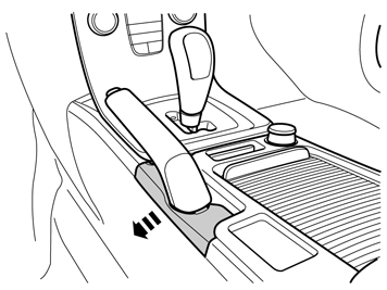
  • Detach the panel by pulling it carefully sideways.

6
IMG-270743
 

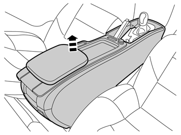
  • Fold up the tunnel console's armrest and remove the cover.

7
IMG-263584
 

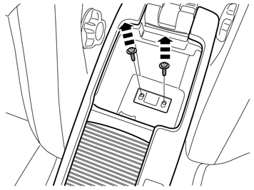
  • Remove the screws.

 
8
IMG-263949
 

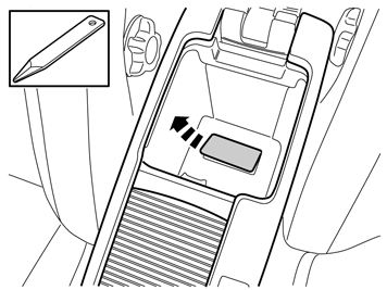
  • Remove the front storage compartment by prying it off at the front edge using a weatherstrip tool and lifting it out.

9
IMG-270744
 

  • Remove the two screws along the front edge of the tunnel console.

10
IMG-263586
 

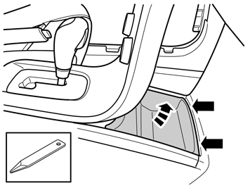
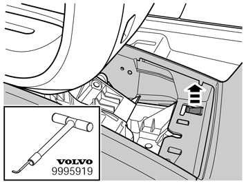
  • Carefully lift the catches at the front edge of the tunnel console.


    Hint

    Use special tool: P/N 9995919.


11
IMG-263208
 

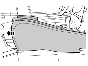
  • At the same time pull the console backwards approximately 20 mm.

12
IMG-263209
 

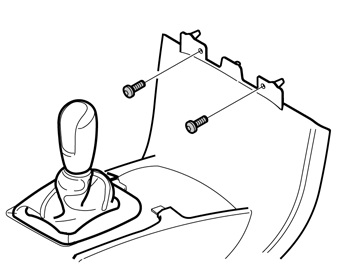
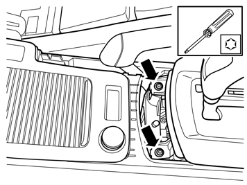
  • Remove the screws.


Applies to vehicles with manual transmissions

13
IMG-270745
 

Applies to vehicles with manual transmissions

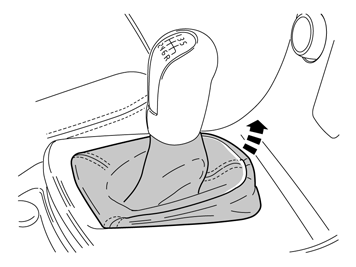
  • Remove the gear selector lever boot from the center console. First pry it off at the front edge using a weatherstrip tool and then unhook it at the rear edge.


Applies to all vehicles

14
IMG-240085
 

Applies to all vehicles

    Remove:

  • the two screws.

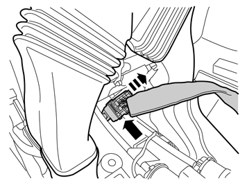
  • the connector to the centre console at the rear.

  • the centre console.

15
IMG-268148
 

  • Lift up the tunnel console and pull it back slightly.

  • Unplug the big gray connector at the front.

16
IMG-271448
 

  • Lift out the tunnel console and turn it upside down.


    Note!

    Protect hand brake and gear lever when removing and installing the tunnel console.


Applies to vehicles with BLIS or DRIVe (not both)

17
IMG-271449
 

Applies to vehicles with BLIS or DRIVe (not both)

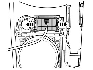
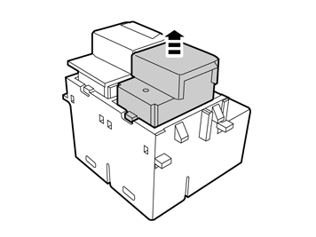
  • Release the catches holding the switch housing and lift out.

18
IMG-271450
 

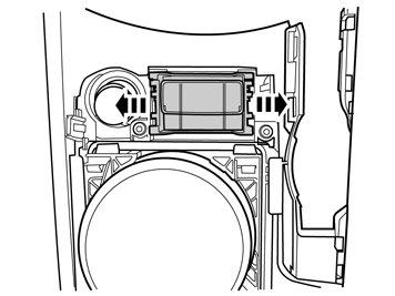
  • Remove the blind cover plug by pulling it straight out.

19
IMG-345634
 

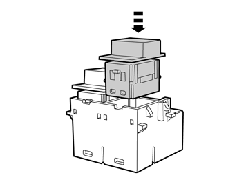
  • Install the switch from the kit.

  • Reinstall the switch housing on the tunnel console.


Applies to vehicles without BLIS and without DRIVe

20
IMG-271451
 

Applies to vehicles without BLIS and without DRIVe

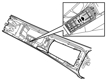
  • Release the catches holding the switch connector and lift out.

  • 21
    IMG-271452
     

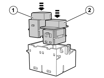
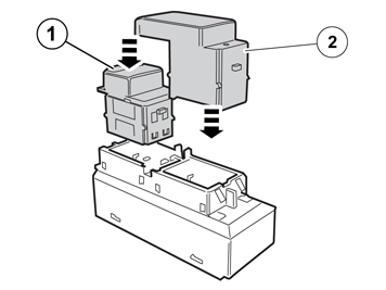
    • Take the switch housing, switch and blind cover plug from the kit. Install the switch (1) and the blind cover plug (2) in the switch housing.

    22
    IMG-271453
     

  • Install the switch housing on the tunnel console.

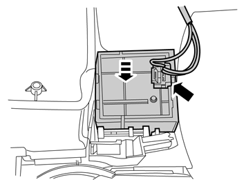
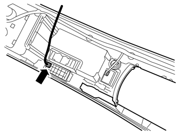
  • Take the cable harness from the kit and connect the blue connector.

  • 23
    IMG-271454
     

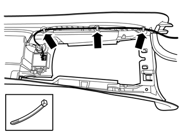
  • Route the cable harness along the existing cable harness. Secure it using three cable ties.

  • 24
    IMG-271465
     

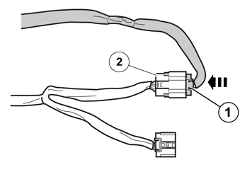
    • Connect the connector (1) from the tunnel console's cable harness to the connector (2) on the prerouted cable harness.

    • Take a piece of foam tape from the kit and wrap it around the connected connectors.


    Applies to vehicles with both BLIS and DRIVe

    25
    IMG-271460
     

    Applies to vehicles with both BLIS and DRIVe

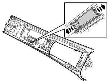
    • Remove the storage compartment from the tunnel console by releasing the catches.

    26
    IMG-271461
     

    • Take the switch housing, switch and blind cover plug from the kit. Install the switch (1) and the blind cover plug (2) in the switch housing.

    27
    IMG-271462
     

    • Install the switch housing on the tunnel console by first hooking it at the rear edge.

    28
    IMG-271463
     

    • Take the cable harness from the kit and connect the green connector to the switch housing.

    29
    IMG-271464
     

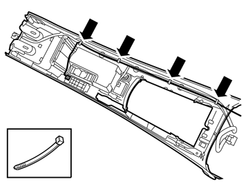
    • Secure the cable harness using four cable ties at the existing cable harness.

    30
    IMG-271465
     

    • Connect the connector (1) from the tunnel console's cable harness to the connector (2) on the prerouted cable harness.

    • Take a piece of foam tape from the kit and wrap it around the connected connectors.


    Applies to all vehicles

    31
     

    Applies to all vehicles

  • Reinstall the detached components in reverse order.

  •  

    Applies to vehicles with both BLIS and DRIVe, as well as vehicles without BLIS and without DRIVe

    32
    IMG-242268
     

    Applies to vehicles with both BLIS and DRIVe, as well as vehicles without BLIS and without DRIVe

    • Run the identification and configuration procedure for the accessory's function according to the service information in VIDA.


    Applies to vehicles with BLIS or DRIVe (not both)

    33
    IMG-242268
     

    Applies to vehicles with BLIS or DRIVe (not both)

    • Run the configuration procedure for the accessory's function according to the service information in VIDA.