|  | | IMG-353176 |
|
| | Applies to cars with decor panel, standard version Performed on 2 sensors.
Applies to cars with decor panel, painted version Performed on 4 sensors.
|
|  | | IMG-353177 |
|
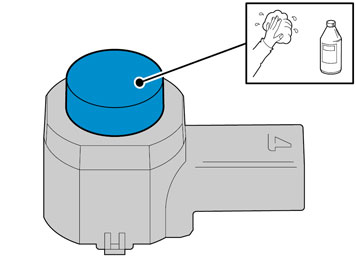
| | Applies to cars with decor panel, standard version Clean 2 sensors. Use: Isopropanol Allow to dry.
Applies to cars with decor panel, painted version Clean 4 sensors. Use: Isopropanol Allow to dry.
|
|  | | IMG-353178 |
|
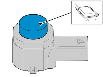
| | Applies to cars with decor panel, standard version Carefully mat down the surface on 2 sensors. Use Glasspaper, grade P1000
Applies to cars with decor panel, painted version Carefully mat down the surface on 4 sensors. Use Glasspaper, grade P1000
|
| | | IMG-353177 |
|
| | |
|  | | IMG-344251 |
|
| | Caution!
Protect the connections' contact surfaces against paint. |
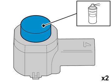
Paint the 2 sensors in the same colour code as the vehicle. Use Volvo Touch-up paint. (Only use base coat.) Use: Volvo 2-K Varnish. P/N: 31335447
Note!
Also read the instructions on the spray can. |
|
| | | IMG-344251 |
|
| | Caution!
Protect the connections' contact surfaces against paint. |
Applies to cars with decor panel, painted version, gloss Use Volvo Touch-up paint. Colour code: 938. (Only use base coat.) Use: Volvo 2-K Varnish. P/N: 31335447
Note!
Also read the instructions on the spray can. |
Applies to cars with decor panel, painted version, matt Use Volvo Touch-up paint. Colour code: 426. (Only use base coat.) Use Volvo Varnish. P/N: 9437467
|
|  | | IMG-353181 |
|
| | Applies to all models Caution!
The paint must have dried after the first application. |
|
|  | | IMG-245980 |
|
| | |
|  | | IMG-245981 |
|
| | |
|  | | IMG-245984 |
|
| | |
|  | | IMG-245985 |
|
| | |
|  | | R3602898 |
|
| | Hold the washer with pliers. Loosen the cover from the nozzle acc. to figure. Let the washer carefully slide back and repeat the step on the car's other side.
Note!
Take care not to scratch the bumper. |
|
|  | | IMG-245986 |
|
| | |
|  | | IMG-245987 |
|
| | Open the engine hood. Remove the 2 screws.
|
|  | | IMG-245988 |
|
| | Lift the bumper casing forward. Loosen the quick-coupling for the headlight washer. Loosen the connector for fog lights. Remove the bumper casing.
|
|  | | IMG-245989 |
|
| | |
|  | | IMG-245990 |
|
| | Localise the markings where the plastic foam was removed. Saw out acc. to the markings with a keyhole saw. At the top edge the slot shall be sawed through the outer casing, plastic foam and inner casing at the same time. Repeat the step on the car's other side.
|
|  | | IMG-245991 |
|
| | |
|  | | IMG-245992 |
|
| | |
|  | | IMG-245993 |
|
| | |
|  | | IMG-245994 |
|
| | |
|  | | IMG-245995 |
|
| | |
|  | | IMG-245996 |
|
| | |
|  | | IMG-245997 |
|
| | Drill holes in the markings' centre with a Ø 3 mm (1/8") drill bit. Drill from the trim panel's and bumper casing's inside. Drill out the holes. Use a Ø10 mm (13/32") diameter drill bit. Enlarge the holes in the trim panel and bumper casing with hole tool part no. 9997234. The hole tool's support sleeve shall be on the inside and the cutting part on the outside of the bumper casing.
|
|  | | IMG-245998 |
|
| | Clean the trim panel's and bumper casing's insides with a mild soap solution. Clean around the holes and the markings using an isopropanol cleaning cloth. Allow to dry. Apply a thin layer of activator, part no. 8637076, to the cleaned surfaces and let dry for approx. 10 min.
|
|  | | IMG-273731 |
|
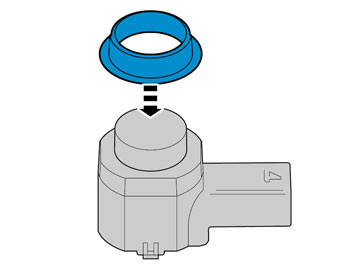
| | Take 4 holders from the kit and clean the surface (1) illustrated using isopropanol. Allow to dry. Apply a thin and even coat of activator to the cleaned surfaces and allow to dry for at least 10 minutes. |
|  | | IMG-245999 |
|
| | |
|  | | IMG-246000 |
|
| | |
|  | | R8504419 |
|
| | |
|  | | R8504171 |
|
| | |
|  | | R8504310 |
|
| | |
|  | | IMG-242247 |
|
| | |
|  | | IMG-246021 |
|
| | |
|  | | IMG-246003 |
|
| | |
|  | | IMG-242240 |
|
| | Applies to cars with two rows of seats Fold up the floor hatch (1). If the floor hatch is equipped with a grocery bag holder, the holder is secured with a strap on both ends of the storage compartment. Detach the straps. Remove the storage compartment under the floor hatch. Remove the floor hatch by folding it almost completely closed and pulling it backwards from the mountings until it releases.
Applies to cars with three rows of seats and integrated carrier bag holder on the underside of the floor hatch Fold up the floor hatch (1). Detach the two straps on the panel under this. Lift up the rear edge of the panel, fold the floor hatch back towards the panel and lift out the floor hatch with the panel.
Applies to cars with three rows of seats without an integrated carrier bag holder Fold up the floor hatch (1) at the rear edge and lift it out.
|
|  | | R8504158 |
|
| | |
|  | | IMG-246004 |
|
| | |
|  | | R3703756 |
|
| | Take the short cable harness from the kit. Remove the taped connector from the cable. Install the larger connector (1) with cable tie/metal clip from the kit. Secure the tie strap around the connector and install the metal clip around the panel edge on the right-hand side of the car.
|
|  | | D2102942 |
|
| | Pull the end of the cable with the loose pins into the engine compartment. Route the cable (1) as illustrated. Place it under the cable duct and expansion tank so that it is concealed.
Note!
Make sure that the cable is positioned so that it is not damaged by heat or wear. |
Clamp it in with tie straps from the kit.
|
|  | | D8200205 |
|
| | Applies to left-hand drive cars Raise the car. Remove the engine splash guard. Remove the plug from the hole in the passenger compartment. It is located under the cowl panel's insulation.
If the car has a rubber grommet without any space for more cables: Remove the existing rubber grommet and replace it with the rubber grommet from the kit. Cut off the tip of one of the rubber teats.
If the car has a rubber grommet with space for more cables: Cut off the tip of the unused rubber teat.
|
|  | | IMG-273732 |
|
| | Applies to left-hand drive cars Route the cable by the cable duct (1) and along behind the drain pipe (2). Secure using a cable tie at the cable duct. Route the cable behind the cowl panel insulation (3) down along to the hole for the rubber grommet. Lubricate the cable with normal soap so that the cable slides easily in the rubber grommet. Thread the rubber grommet on the cable. Route the cable in through the hole and press in the rubber bushing in the hole so that it seals properly. Pull the cable again so that the correct length remains outside the passenger compartment. Make sure that the cable's heating hose is in contact against the rubber grommet and secure it with a tie strap. |
|  | | IMG-217620 |
|
| | Applies to right-hand drive cars. Localise the rubber bushing for the wire to the hood lock. Cut off the tip of an unused rubber teat. Insert e.g. a welding wire or a wire through the rubber bushing and tape the cable on the welding wire/wire. Lubricate the cable with normal soap so that the cable slides easily in the rubber grommet. Route the welding wire/wire and cable in through the rubber bushing. Adjust it so that the correct length remains outside the passenger compartment. Seal between the rubber grommet and cabling by fitting a tie strap around the rubber teat. Make sure that the cable's heating hose is in contact against the rubber grommet and secure it with a tie strap.
|
|  | | J3703487 |
|
| | Applies to all models Take the connector and loosen the lock. Install the cable ends' pins in the connector acc. to: 1. Blue (BL) 2. Green (GN) 3. Violet (VO) 4. Yellow (Y) 5. White (W) 6. Black (SB) Press back the connector's catch.
|
|  | | R8505178 |
|
| | |
|  | | R3702904 |
|
| | Guide the cable down between the carpet and the door sill as far as possible to the floor and route it along the right-hand side of the car on to the rear edge of the right-hand rear door's opening. Route the cable by the front right-hand seat mounting on the right-hand seat in the second row of seats. Pull away the mat from the front edge of the right-hand side panel in the cargo compartment. Route the cable harness along the right side of the right seat's placement in the second row of seats, towards the front edge of the rear wheel housing. Route it further on the left-hand side of the seat belt's lower mounting, between the support bracket for the right-hand seat and wheel housing, and out at the left-hand side of the wheel housing. Clamp the cable harness into the hole in the seat mounting front member, and in the rear hole in the horizontal panel at the right-hand side of the seat. Use tie straps (1) from the kit.
|
|  | | R3702907 |
|
| | Applies to cars with three rows of seats Guide in a wire or cable (1) at the rear edge of the right-hand side panel and along its inside, above the load securing eyelet brackets. Route the wire/cable to the front edge of the side panel.
|
|  | | R3703023 |
|
| | Applies to cars with three rows of seats Tape the cable (2) to the wire and route it on at the rear edge of the side panel.
|
|  | | R8505187 |
|
| | Applies when the rear side panel must be removed to facilitate cable routing. Remove: four covers. four screws. one clip. Detach the C and D panels at the lower edge. Pull the side panel away and lift it off.
|
|  | | R3702935 |
|
| | Applies to cars with two rows of seats Route the cable on the left-hand side of the seat belt's mounting at the front edge of the wheel housing, inside the carpet at the front edge of the side panel, between the side panel and the rear cargo floor support, to the tailgate.
|
|  | | IMG-246005 |
|
| | |
|  | | IMG-246006 |
|
| | |
|  | | IMG-246007 |
|
| | Connect the routed cable's connector to the middle connection. Reinstall the control module. Return to the work with the bumper casing.
|
|  | | IMG-246008 |
|
| | |
|  | | IMG-246009 |
|
| | |
|  | | IMG-246010 |
|
| | |
|  | | IMG-246011 |
|
| | |
|  | | IMG-246012 |
|
| | |
|  | | IMG-246013 |
|
| | |
|  | | IMG-246014 |
|
| | |
|  | | IMG-246015 |
|
| | |
|  | | IMG-246016 |
|
| | |
|  | | IMG-246017 |
|
| | |
|  | | IMG-246018 |
|
| | Assemble outer and inner casing and, at the same time, insert the cable harness through the inner casing.
Note!
Make sure that all catches fully engage. |
Reinstall the headlight washers.
|
|  | | IMG-246019 |
|
| | Hold the bumper up against the car and connect the connector for the sensors to the connector clamped to the car. Reinstall the bumpers by repeating the instructions in the steps for removal in reverse order.
Install: the sound barrier the sill trim panels side panel on the centre console. panel over the joint between the door sills the seatbelt
Note!
Check that the seat belt is secure by jerking it hard in an upwards direction. |
The seat, torque screws with 50 Nm (36.8 lbf.ft.) the seat panels the side panels the floor hatches.
|
|  | | IMG-242268 |
|
| | |