| | |
|  | | IMG-335491 |
|
| | |
|  | | IMG-268003 |
|
| | |
|  | | IMG-268004 |
|
| | |
|  | | IMG-268005 |
|
| | |
|  | | IMG-268006 |
|
| | |
| | |
|  | | IMG-268007 |
|
| | |
|  | | IMG-268009 |
|
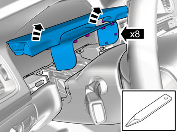
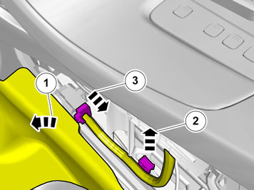
| | Remove the screw at the lower edge of the trunk lid's upper panel, on both sides. Unhook the lower edge of the panel from the lower panel, on both sides.
|
|  | | IMG-268011 |
|
| | |
|  | | IMG-268010 |
|
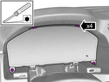
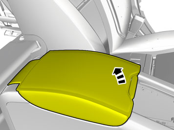
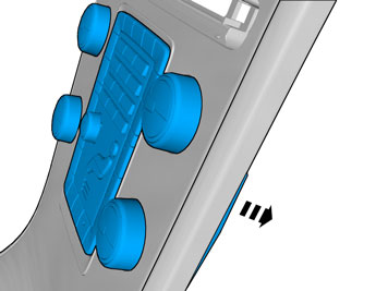
| | Remove the lower panel by prying it off around the edge using a weatherstrip tool. Then carefully pull it off so that all the clips on the inside release. If the car is equipped with an electric door closer, remove its connector.
|
| | Cargo compartment preparations |
|  | | IMG-268012 |
|
| | Cargo compartment preparations |
|  | | IMG-268013 |
|
| | |
|  | | IMG-268014 |
|
| | |
|  | | IMG-268015 |
|
| | |
|  | | IMG-259759 |
|
| | |
|  | | IMG-268016 |
|
| | |
| | |
|  | | IMG-268017 |
|
| | |
|  | | IMG-268018 |
|
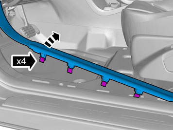
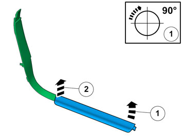
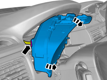
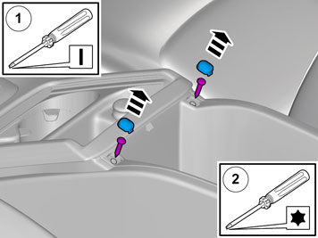
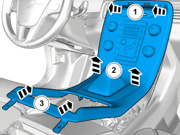
| | Fold the left-hand backrest forward. Remove the side cushion on the left by first pulling it backwards at the upper edge until the hooks (1) release. Then pull it inwards slightly until the hook (2) releases, and upwards until the locating pin (3) disengages from the mounting at the rear edge.
|
|  | | IMG-268024 |
|
| | |
|  | | IMG-268025 |
|
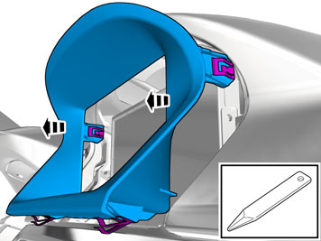
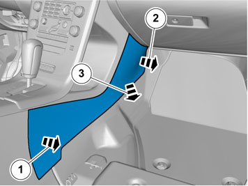
| | Carefully pull off the top panel from the side panel, it is secured by a clip at the front edge and a locating pin at the rear edge. Unhook the seat belt and place the panel to one side.
|
|  | | IMG-268026 |
|
| | |
|  | | IMG-268027 |
|
| | |
| | |
|  | | IMG-353617 |
|
| | |
|  | | IMG-353618 |
|
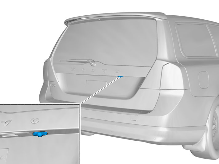
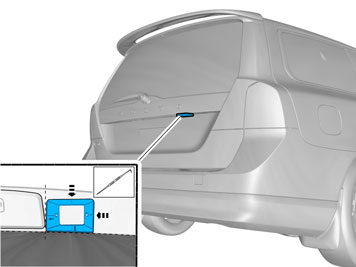
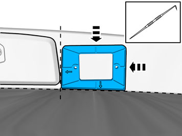
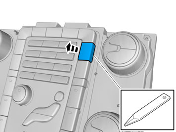
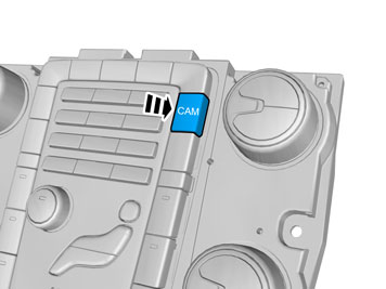
| | Remove the license plate and holder. Take the template from the kit. Place it to the right of the plate lighting panel, so that it is against it and against the trunk lid's vertical section. The template must be turned so that the small arrow marks in the template are visible, and position as illustrated.
Caution!
It is important that the template is positioned correctly and is turned as illustrated so that the camera is correctly positioned in the trunk lid. |
Take a scriber and make marks for sawing and drilling holes for screws and the camera.
|
|  | | IMG-268029 |
|
| | |
|  | | IMG-268030 |
|
| | First drill a hole for the saw blade. Carefully saw out the hole following the inside of the marking. The marking should remain visible. Adjust the size of the hole using a file if necessary. Remove any swarf.
|
|  | | IMG-268031 |
|
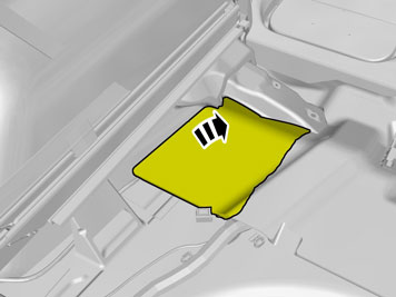
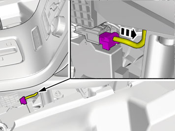
| | Make a Ø25 mm (1" ) hole for the cable to the camera at the right lower section of the trunk lid, approximately where illustrated.
Note!
Hold the belt for the wiper motor to one side to prevent damaging it whilst drilling. |
Even off the edges using a fine file. Remove any swarf.
|
|  | | IMG-268032 |
|
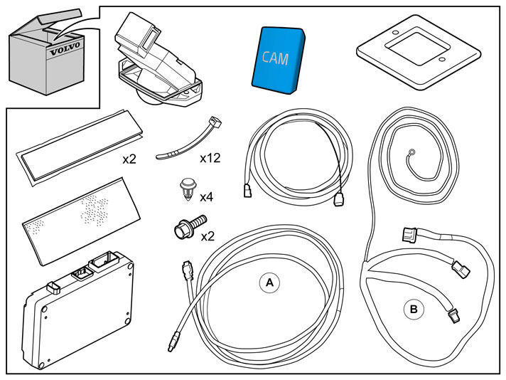
| | Take the cable harness marked A in the kit image. Insert the cable end with the yellow marking through the drilled hole in the trunk lid. Place the template over the hole inside the trunk lid. The template must be turned with the arrow markings towards the trunk lid. Insert the cable into the hole.
|
|  | | IMG-268033 |
|
| | |
|  | | IMG-268034 |
|
| | Screw the right-hand screw fully in the camera. Align the template so that the right-hand hole in the template is directly above the right-hand hole in the lid. Hold the template in position (inside the hole in the trunk lid) and, at the same time, tighten the camera's right-hand screw so it holds. Align the left-hand holes with each other, fit the screw and tighten the camera.
|
| | |
|  | | IMG-268035 |
|
| | |
|  | | IMG-268036 |
|
| | |
|  | | IMG-268037 |
|
| | |
|  | | IMG-287103 |
|
|  | | IMG-287104 |
|
| | |
|  | | IMG-268040 |
|
| | |
|  | | IMG-268041 |
|
| | |
|  | | IMG-268042 |
|
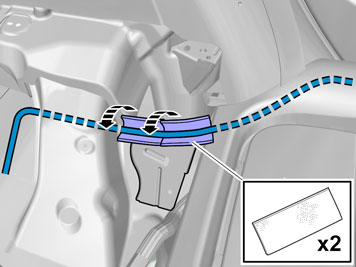
| | Place the cable harness from the camera inside the contact strip to the rear window's heating elements. Secure the cable harness with pieces of butyl tape. Clamp the cable harness where is crosses the existing cable harness, use a cable tie from the kit.
|
|  | | IMG-268043 |
|
| | |
|  | | IMG-268044 |
|
| | Insert a piece of wire through the rubber grommet. Tape the connector at the wire securely. Also, position the wire slightly out on the cable so that the connector does not take all the strain when the cable is pulled through. Now tape the wire at the connector and cable.
|
|  | | IMG-268045 |
|
| | |
|  | | IMG-268047 |
|
| | |
|  | | IMG-268048 |
|
|  | | IMG-268465 |
|
| | Illustration A Take the receptacle housing section of the connector with the two metal strips from the kit. Carefully place the connector in the receptacle housing section with the round section (1) of the connector aligned in the corresponding cut-out (1) in the receptacle housing section. The upturned section (2) of the connector must also be aligned in the corresponding cut-out in the receptacle housing section.
Illustration B Carefully place the other receptacle housing section on the connector. The upturned section (2) of the connector must be aligned in the corresponding cut-out in the receptacle housing section. Press the receptacle housings and connector together until the four catches engage.
|
|  | | IMG-268049 |
|
| | |
|  | | IMG-268050 |
|
| | |
|  | | IMG-268051 |
|
| | |
|  | | IMG-268052 |
|
| | |
|  | | IMG-268053 |
|
| | Route the cable harness to the left towards the D pillar. Clamp above the ceiling panel at the existing cable harness using two cable ties. Route at the D pillar along the existing cable harness to the front edge of the fuse holder. Secure using three cable ties.
|
|  | | IMG-268054 |
|
| | Continue to route the cable harness along the existing cable harness, under the rail, and forward between the brackets to the rail and wheel housing. Secure at the existing cable harness using two cable ties.
|
| | Installing the parking assistance camera (PAC) |
|  | | IMG-353732 |
|
| | Installing the parking assistance camera (PAC) |
|  | | IMG-287223 |
|
| | |
|  | | IMG-287123 |
|
| | |
|  | | IMG-255751 |
|
| | |
|  | | IMG-261496 |
|
| | |
|  | | IMG-222282 |
|
| | |
|  | | IMG-241925 |
|
| | |
|  | | IMG-255752 |
|
| | |
|  | | IMG-255753 |
|
| | |
|  | | IMG-287147 |
|
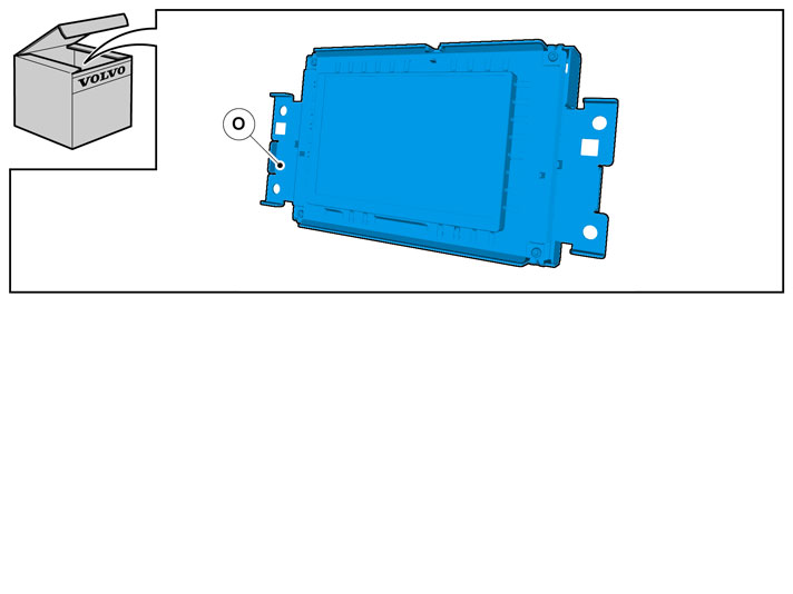
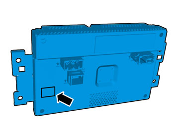
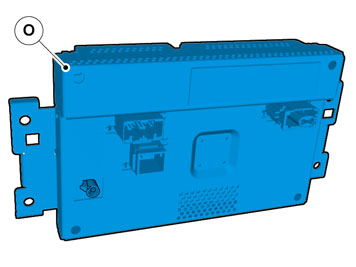
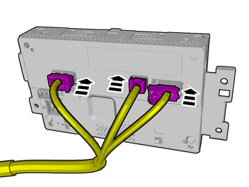
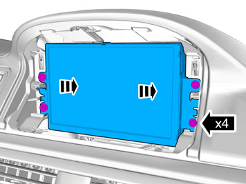
| | Position the control module on the floor so that it fits in the cut-out in the insulation. Secure the control module to the floor. Connect the routed cable connector to the control module.
|
|  | | IMG-287143 |
|
|  | | IMG-287144 |
|
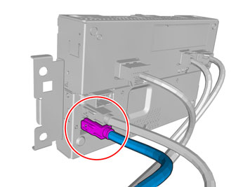
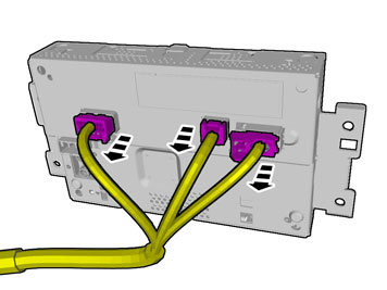
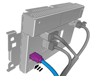
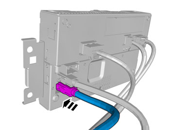
| | Illustration A Take the adapter cable B with the green connector from the kit. Connect the green 16 pin connector to the control module. Connect the green prerouted 5-pin male connector to the corresponding connector in the adapter cable. Secure the excess cable at the existing using a cable tie.
Image B applies to cars with trailer module (TRM): The image shows the location of the control module for the parking assistance camera (PAC) together with the trailer module (TRM). Ensure that the control module for the parking assistance camera is positioned so that it and the wiring do not rub against the trailer module (TRM). Disconnect the green 5-pin male connector (1) from the trailer module (TRM) and connect to the green 5-pin female connector (2) in the adapter cable. Connect the remaining green connectors (3) in the adapter cable to the parking assistance camera module and the trailer module (TRM).
|
|  | | IMG-353733 |
|
| | |
|  | | IMG-353734 |
|
| | |
|  | | IMG-353735 |
|
| | |
|  | | IMG-353736 |
|
| | Wash the rear crossmember using isopropanol where the ground lead is to be taped. Wipe dry. Use a wide piece of tape, silver tape/duct tape or similar.
Note!
The ground lead must only be taped at the rear crossmember, it must not be secured by the thick cable harness. |
|
| | Preparations, passenger compartment |
|  | | IMG-346689 |
|
| | Preparations, passenger compartment |
|  | | IMG-338119 |
|
| | |
|  | | IMG-346676 |
|
| | |
|  | | IMG-346681 |
|
| | |
|  | | IMG-346677 |
|
| | |
|  | | IMG-346682 |
|
| | |
|  | | IMG-344717 |
|
| | |
|  | | IMG-344721 |
|
| | |
|  | | IMG-344722 |
|
| | |
|  | | IMG-341879 |
|
| | |
|  | | IMG-341941 |
|
| | |
|  | | IMG-349876 |
|
| | |
|  | | IMG-349877 |
|
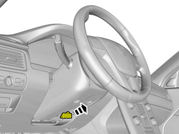
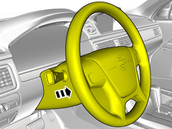
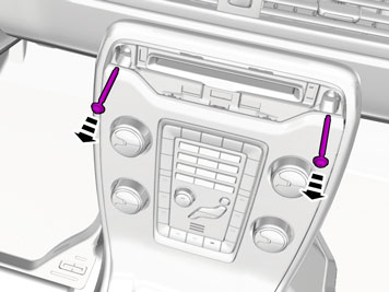
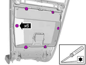
| | Remove the screws. Remove the panel.
|
|  | | IMG-348526 |
|
| | Vehicles with 5 inch ICM display Note!
If there is no connection, replace the display. |
|
|  | | IMG-352166 |
|
| | Vehicles with 7 inch display Disconnect the connector, if applicable. use electrical tape to secure the connector in the existing cable.
|
|  | | IMG-345776 |
|
| | Applies to all models Note!
The number of connectors, cables and cable ties can vary depending on the vehicle's equipment level. |
|
|  | | IMG-287145 |
|
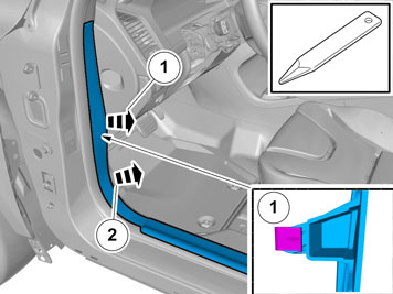
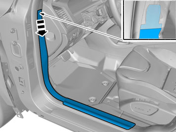
| | Take the remaining cable harness and connect it to the control module. Route it under the member at the wheel housing, under the insulation and up to the door opening at the left-hand rear door.
|
|  | | IMG-354975 |
|
| | |
| | | IMG-241925 |
|
| | |
|  | | IMG-353731 |
|
| | |
|  | | IMG-255771 |
|
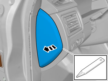
| | Pull out the B pillar panel at the lower edge until the two clips release. Continue to route the cable harness inside the B pillar panel and forwards in the car. Route the cable harness along the left-hand side, in front of the floor and insulation panels, up to the front edge of the door opening.
|
|  | | IMG-353574 |
|
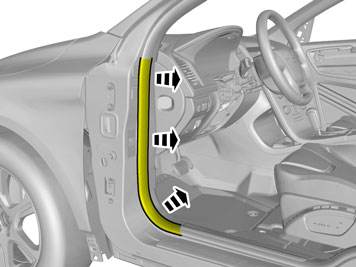
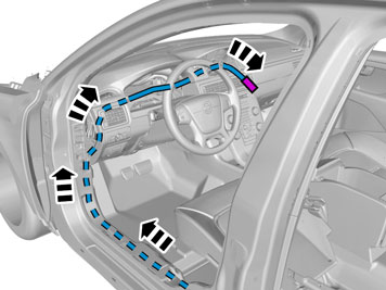
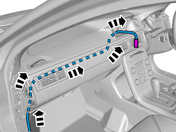
| | Only applies to left-hand drive vehicles Route the cable harness inside the floor and insulation panels, up on the A pillar slightly, and then at an angle upwards, between the A pillar and the end panel, towards the dashboard. Route the cable harness to the location for the screen in the dashboard. Place the cable harness so that it does not come into contact with sharp edges or moving parts under the dashboard.
|
|  | | IMG-353581 |
|
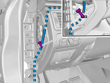
| | Only applies to right-hand drive vehicles Take a piece of wire and insert it by the air ducts through the hole for the screen. Pull it out to the left, above the glove compartment and out through the left-hand end of the dashboard. Tape the connector on the cable to the screen by the wire. Pull the cable up to the location for the screen and out through the hole in the dashboard.
|
|  | | IMG-353636 |
|
| | |
|  | | IMG-255775 |
|
| | Only applies to left-hand drive cars |
| | | IMG-348526 |
|
| | Applies to all vehicles with 5 inch ICM display Note!
If there is no connection, replace the display. |
|
|  | | IMG-348747 |
|
| | |
|  | | IMG-348748 |
|
| | Applies to all vehicles Note!
The number of connectors, cables and cable ties can vary depending on the vehicle's equipment level. |
|
|  | | IMG-352266 |
|
| | Applies to vehicles with 5 inch ICM display |
|  | | IMG-352267 |
|
| | Applies to vehicles with 7 inch display |
|  | | IMG-349904 |
|
| | |
| | |
|  | | IMG-349804 |
|
| | |
|  | | IMG-349806 |
|
| | |
|  | | IMG-345282 |
|
| | |
|  | | IMG-339505 |
|
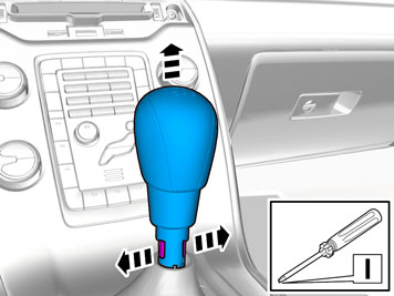
| | Applies to vehicles with manual transmissions |
|  | | IMG-347222 |
|
| | |
|  | | IMG-345283 |
|
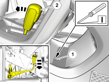
| | Cars with automatic transmissions |
|  | | IMG-345284 |
|
| | |
|  | | IMG-292804 |
|
| | |
|  | | IMG-340599 |
|
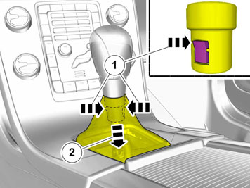
| | Fold back the mat. Unhook the cable harness clips. Unplug the connector.
|
|  | | IMG-341780 |
|
| | |
|  | | IMG-349811 |
|
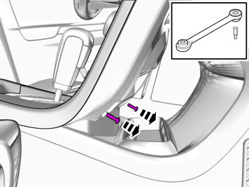
| | Remove the covers. Remove the screws.
|
|  | | IMG-292826 |
|
| | Vehicles with the 4C system |
|  | | IMG-345317 |
|
| | |
|  | | IMG-349826 |
|
| | Applies to all vehicles Caution!
Do not damage the hooks. |
|
|  | | IMG-345295 |
|
| | |
|  | | IMG-345296 |
|
| | |
|  | | IMG-345763 |
|
| | |
|  | | IMG-353616 |
|
| | |
|  | | IMG-336901 |
|
| | |
|  | | IMG-336904 |
|
| | Warning!
When the ignition is to be switched on for the first time after the battery has been disconnected, this must be done whilst by standing outside the vehicle, stretching your arm in and avoiding the working area for the airbags. |
|
|  | | IMG-242268 |
|
| | |
|  | | IMG-354602 |
|
| | Perform a function test as follows Engage reverse gear. The display is activated. Wait for the message "Update Environment" to appear on the screen. Follow the on-screen instructions. Switch off the ignition for at least 10 seconds. Turn the ignition on. The display is activated. Check that the support lines appear on the screen and that these react to steering wheel movements.
|