| | |
|  | | IMG-297204 |
|
|  | | IMG-297185 |
|
| | |
|  | | IMG-297503 |
|
| | |
|  | | IMG-297504 |
|
|  | | IMG-297523 |
|
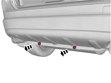
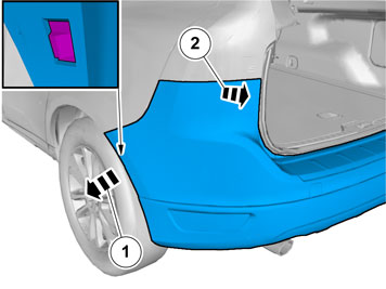
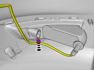
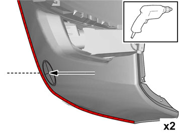
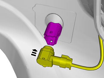
| | Illustrations A and B Note!
This procedure is easier carried out by two people. |
|
|  | | IMG-285054 |
|
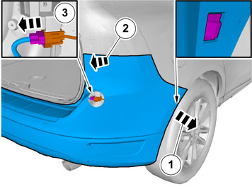
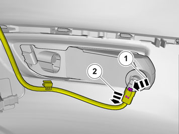
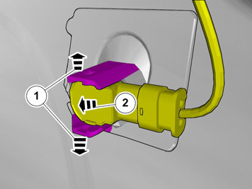
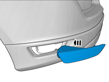
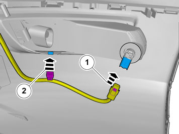
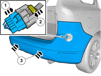
| | Applies to vehicles with parking assistance Release the connector's catch. Disconnect the connector(s). Position the bumper so that it does not become damaged.
|
|  | | IMG-338197 |
|
|  | | IMG-338198 |
|
|  | | IMG-338199 |
|
| | Applies to all models Illustrations A, B and C |
|  | | IMG-338200 |
|
|  | | IMG-338201 |
|
| | Applies to vehicles with parking assistance Illustrations A and B |
|  | | IMG-338202 |
|
|  | | IMG-338203 |
|
| | |
|  | | IMG-337641 |
|
| | |
|  | | IMG-285095 |
|
| | Applies to vehicles with a towbar |
|  | | IMG-285512 |
|
| | Applies to vehicles with a detachable towbar |
|  | | IMG-285513 |
|
| | Applies to vehicles with a detachable towbar Note!
Do not damage the surface of the skid plate. Cut so that the raised edge on the inside remains. The raised edge marks the cut-out. |
|
|  | | IMG-295363 |
|
| | Applies to vehicles with a fixed towbar |
|  | | IMG-285096 |
|
| | Applies to vehicles with a fixed towbar Note!
Do not damage the surface of the skid plate. Cut so that the raised edge on the inside remains. The raised edge marks the cut-out. |
|
|  | | IMG-295746 |
|
| | Applies to vehicles with a towbar hitch |
|  | | IMG-295747 |
|
| | Applies to vehicles with a towbar hitch Note!
Do not damage the surface of the skid plate. Cut so that the raised edge on the inside remains. The raised edge marks the cut-out. |
|
|  | | IMG-337680 |
|
| | |
|  | | IMG-337682 |
|
| | |
|  | | IMG-331352 |
|
| | Applies to vehicles with parking assistance |
|  | | IMG-331358 |
|
| | |
|  | | IMG-331359 |
|
| | |
|  | | IMG-331350 |
|
|  | | IMG-331348 |
|
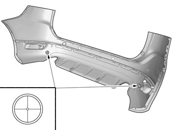
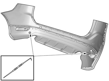
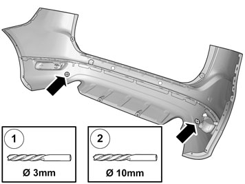
| | Illustrations A and B Ø 3 mm (7/64") Ø 10 mm (25/64")
Caution!
Drill horizontally through the bumper cover. |
|
|  | | IMG-331360 |
|
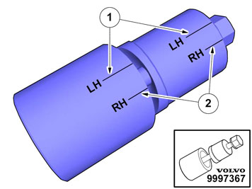
| | Caution!
Place the hole tool's support sleeve on the inside, and the cutting part on the outside of the bumper casing. |
|
|  | | IMG-331355 |
|
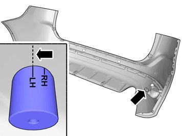
| | Applies to the left-hand side Note!
Ensure that the support sleeve does not turn when the screw is tightened. |
|
|  | | IMG-331356 |
|
| | Applies to the right-hand side Note!
Ensure that the support sleeve does not turn when the screw is tightened. |
|
|  | | IMG-338106 |
|
| | |
|  | | IMG-338108 |
|
| | |
|  | | IMG-339321 |
|
| | |
|  | | IMG-338111 |
|
| | |
|  | | IMG-338136 |
|
| | |
|  | | IMG-338148 |
|
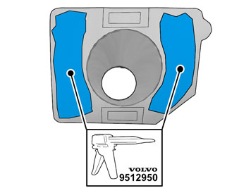
| | Apply a thin and even layer of adhesive. The adhesive must be above the tape level. Use: 9512950 Adhesive gun, 1161730 Mixing pipe and 9511027 Adhesive.
Caution!
The adhesive must not come into contact with the tape. |
|
|  | | IMG-297576 |
|
| | |
|  | | IMG-337687 |
|
| | |
|  | | IMG-297604 |
|
| | Applies to vehicles with parking assistance |
|  | | IMG-338196 |
|
| | Applies to vehicles without parking assistance |