| | |
|  | | IMG-221940 |
|
| | |
|  | | IMG-222060 |
|
| | |
|  | | IMG-226340 |
|
| | |
|  | | IMG-226341 |
|
| | |
|  | | IMG-222063 |
|
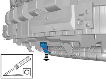
| | Note!
It is easier if two people work to remove the bumper. |
Pull the bumper straight back until the catches below the tail lamps release. Disconnect any parking assistance connectors. Place the bumper on a surface that will not damage the paint.
|
|  | | IMG-338916 |
|
| | |
|  | | IMG-225745 |
|
| | |
| | |
|  | | IMG-227760 |
|
| | Installation Clean any underseal and dirt from the inner member of the bumper where the L-profile for the towbar is to be located. Clean the metal flange on the inside and outside where the reinforcement stay is to be located.
|
|  | | J8903194 |
|
| | |
|  | | IMG-241886 |
|
| | |
|  | | IMG-241888 |
|
|  | | IMG-280323 |
|
| | Illustration A Applies to vehicles with 5-cylinder engine Place a support under the muffler. Detach the silencer's rubber mounting from its brackets on the right and left-hand side.
Applies to vehicles with 5-cylinder engine On some versions, the rear muffler has 2 rubber mountings on each side. The rear ones must be removed completely and not reused.
|
|  | | IMG-242363 |
|
| | Applies to vehicles with 5-cylinder engine Remove the screws and brackets of the muffler mount on the right and left side.
|
|  | | J8903549 |
|
| | Applies to vehicles with 4-cylinder engine Detach the rubber mounting for the end pipes from the bracket on the underneath of the left side member. Remove the screw and the bracket.
|
|  | | IMG-271069 |
|
| | |
|  | | IMG-280324 |
|
| | |
|  | | IMG-280325 |
|
| | |
|  | | IMG-359839 |
|
| | |
|  | | IMG-280927 |
|
| | Tighten the L profile's four M10 screws (1) alternatingly so that the L profile and the inner member of the bumper lie against each other correctly. Tightening torque: 47 Nm (35 lbf.ft). Tighten the four M10 screws (2) of the towbar retainer and reinforcement stay alternatingly. Tightening torque: 47 Nm (35 lbf.ft). Tighten the two M14 screws (3). Tightening torque: 200 Nm (147 lbf.ft). Tighten the six screws (4) for the reinforcement stay's front attachments in steps. Tightening torque 20 Nm (15 lbf.ft.) and then angle-tighten 90°. There is not a lot of room to torque-tighten the middle screw, use special tool part no. 9997361with a 3/8" socket extension.
|
|  | | IMG-271071 |
|
|  | | IMG-338246 |
|
|  | | IMG-338247 |
|
| | Illustration A: Applies to all Refit the rubber mounting. Remove the support from under the muffler. Install the towbar wiring following separate installation instructions.
Illustrations B & C: Apply to vehicles with engine D5204T/T5 |
|  | | IMG-225762 |
|
| | |
|  | | IMG-225809 |
|
| | Connect any parking assistance connectors and reinstall the bumper. Press so that the hooks under the tail lamps engage. Press until the catches for both ends of the bumper shell engage. Reinstall the screws. Check the function of the detachable towbar. See handling instructions.
|
| | |
|  | | IMG-225810 |
|
| | Storing the towbar Applies to vehicles without spare wheel |
|  | | IMG-225845 |
|
| | Steps 23-25 apply to vehicles with spare wheel |
|  | | IMG-225811 |
|
| | |
|  | | IMG-225812 |
|
| | |
| | |
|  | | IMG-241905 |
|
| | |
|  | | IMG-226909 |
|
| | |
|  | | IMG-227105 |
|
| | Press the protective cover into the cradle until it lies against the bumper cover. A number of clicks should be heard when the protective cover is pressed into place. Check that the protective cover lies against the bumper cover Check that the protective casing is fitted securely.
|
|  | | IMG-261586 |
|
| | |
|  | | IMG-359307 |
|
| | Applies to cars with engine D5204T or D5204T5 |
|  | | IMG-359317 |
|
| | |
|  | | IMG-359328 |
|
| | |
|  | | IMG-359308 |
|
| | |
|  | | IMG-359332 |
|
| | |
|  | | IMG-359364 |
|
| | |
|  | | IMG-359365 |
|
| | |
|  | | IMG-359366 |
|
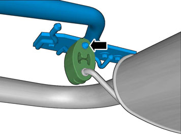
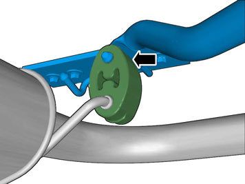
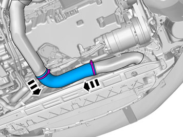
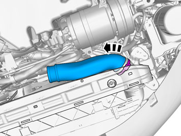
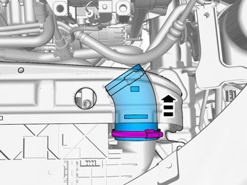
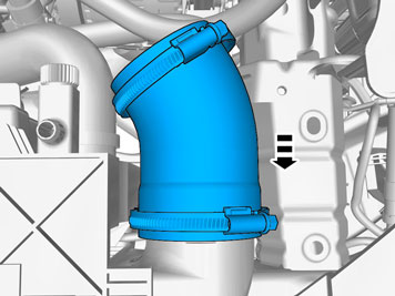
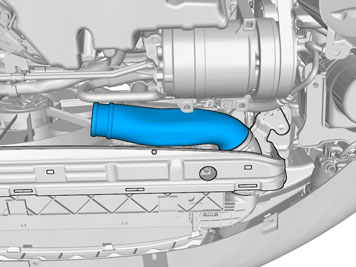
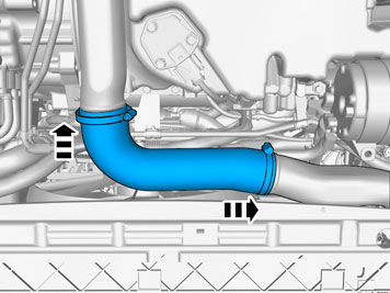
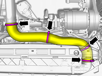
| | Detach the hose clamp. Remove the pipe.
|
|  | | IMG-359371 |
|
| | |
|  | | IMG-359372 |
|
| | |
|  | | IMG-359376 |
|
| | |
|  | | IMG-359377 |
|
| | |
|  | | IMG-359379 |
|
| | |