| | |
| | Read through all of the instructions before starting installation. Notifications and warning texts are for your safety and to minimise the risk of something breaking during installation. Ensure that all tools stated in the instructions are available before starting installation. Certain steps in the instructions are only presented in the form of images. Explanatory text is also given for more complicated steps. In the event of any problems with the instructions or the accessory, contact your local Volvo dealer.
|
| | This instruction covers a Plug-In Hybride vehicle. |
|  | | IMG-373194 |
|
| | Warning!
Observe caution when working near the high voltage system. |
This car is equipped with a high voltage type electrical system. Components in the high voltage system work with dangerous voltages. These components are connected with orange wires. |
| | |
|  | | IMG-363036 |
|
| | Note!
This colour chart displays (in colour print and electronic version) the importance of the different colours used in the images of the method steps. |
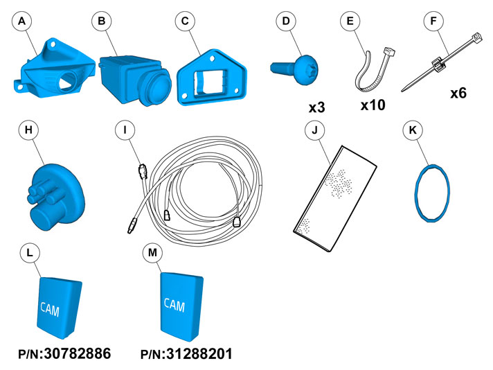
Used for focused component, the component with which you will do something. Used as extra colors when you need to show or differentiate additional parts. Used for attachments that are to be removed/installed. May be screws, clips, connectors, etc. Used when the component is not fully removed from the vehicle but only hung to the side. Used for standard tools and special tools. Used as background color for vehicle components.
|
| | |
|  | | IMG-332193 |
|
| | Set the ignition key to position 0. |
|  | | IMG-385431 |
|
| | |
|  | | IMG-292806 |
|
| | |
|  | | IMG-292823 |
|
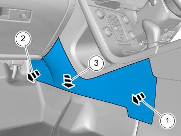
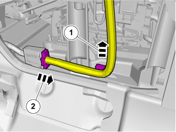
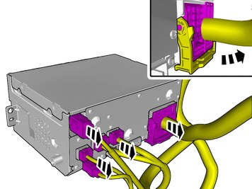
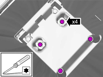
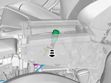
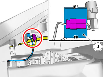
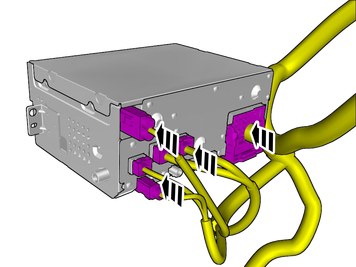
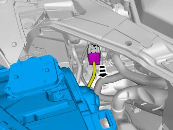
| | Remove the cable harness clips. Disconnect the connector. |
|  | | IMG-385432 |
|
| | |
|  | | IMG-292827 |
|
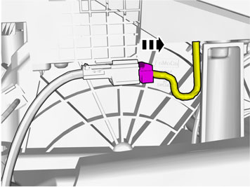
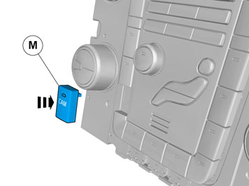
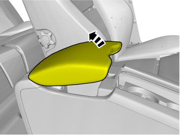
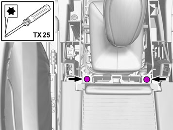
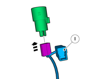
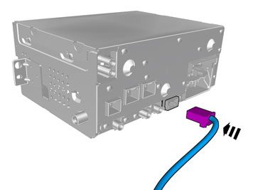
| | Disconnect the connector. |
|  | | IMG-385434 |
|
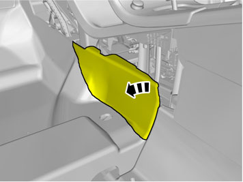
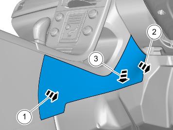
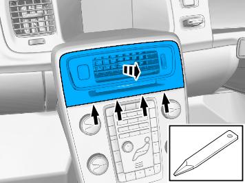
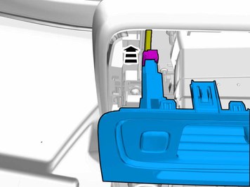
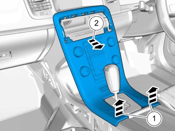
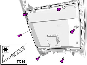
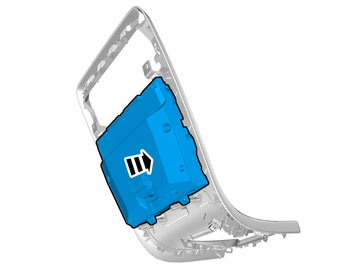
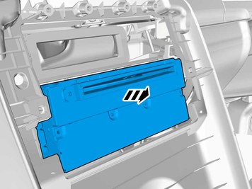
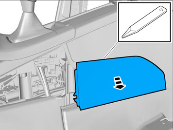
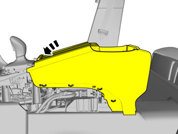
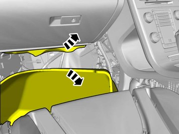
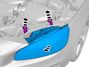
| | Carefully pry loose the bottom edge of the panel and then continue around the panel. |
|  | | IMG-385435 |
|
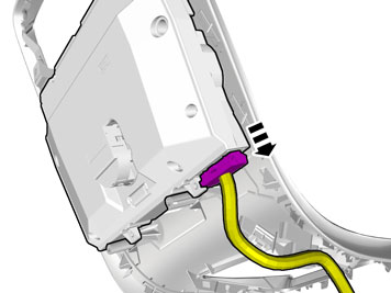
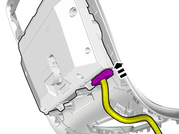
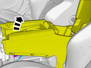
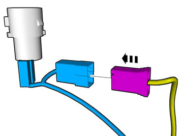
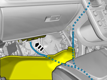
| | Disconnect the connector. |
|  | | IMG-385436 |
|
| | |
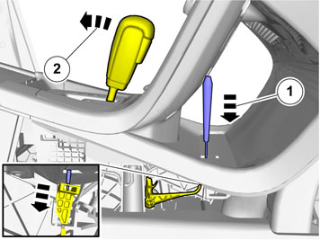
|  | | IMG-355818 |
|
| | |
| | Cars with automatic transmissions |
|  | | IMG-293006 |
|
| | |
|  | | IMG-293007 |
|
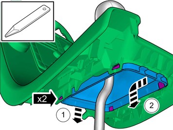
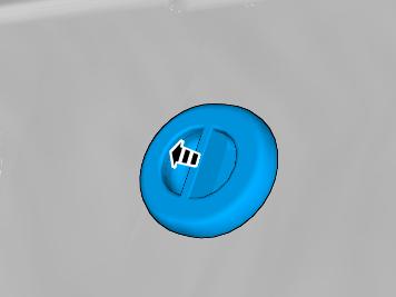
| | Release the shift-lock function. |
| | |
|  | | IMG-385437 |
|
| | |
| | Cars with manual transmissions |
|  | | IMG-385438 |
|
| | |
| | |
|  | | IMG-340604 |
|
| | Disconnect the connector. |
|  | | IMG-340605 |
|
| | |
|  | | IMG-340607 |
|
| | |
|  | | IMG-380815 |
|
| | |
| | |
|  | | IMG-380819 |
|
| | |
|  | | IMG-380816 |
|
| | Install component that comes with the accessory kit. |
| | |
|  | | IMG-341739 |
|
| | |
| | | IMG-340605 |
|
| | |
|  | | IMG-340622 |
|
| | |
| | |
|  | | IMG-340988 |
|
| | |
|  | | IMG-385445 |
|
| | |
|  | | IMG-380933 |
|
| | Disconnect the connectors. |
|  | | IMG-293021 |
|
| | |
|  | | IMG-293022 |
|
| | |
|  | | IMG-293023 |
|
| | |
|  | | IMG-377998 |
|
| | |
|  | | IMG-345746 |
|
| | |
|  | | IMG-374497 |
|
| | |
|  | | IMG-374495 |
|
| | Disconnect the connector. |
| | |
|  | | IMG-374547 |
|
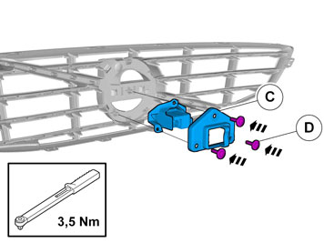
| | Install component that comes with the accessory kit. |
|  | | IMG-362040 |
|
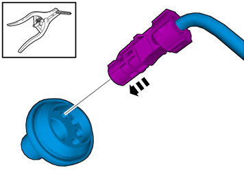
| | Locate the existing connector in the vehicle's cable harness. Connect the connector. |
|  | | IMG-382650 |
|
| | |
|  | | IMG-374510 |
|
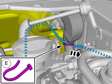
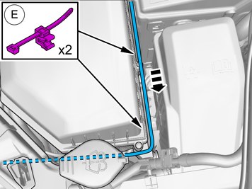
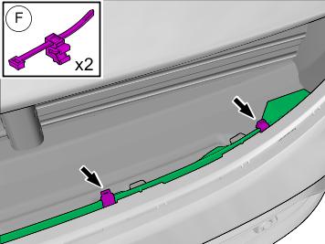
| | Tear off the excess foam tape. Clamp the cables and connectors to the existing cables to prevent noise. |
|  | | IMG-380968 |
|
| | |
|  | | IMG-380969 |
|
| | |
|  | | IMG-380941 |
|
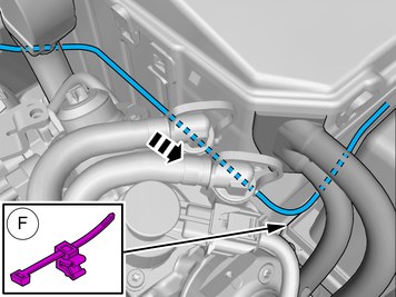
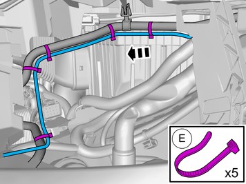
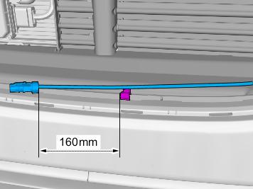
| | Connect the prerouted cable. |
|  | | IMG-380943 |
|
| | |
|  | | IMG-385472 |
|
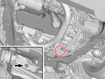
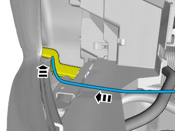
| | Fold the carpet aside. Locate the rubber grommet under the insulating mat. |
|  | | IMG-385185 |
|
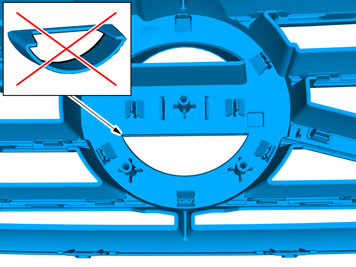
| | The part is not to be reused. |
|  | | IMG-385473 |
|
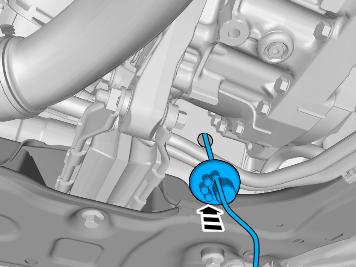
| | Pull the wiring through. Fold the floor carpet back. |
| | |
|  | | IMG-377070 |
|
| | Reinstall the removed parts in reverse order. |
| | |
|  | | IMG-385035 |
|
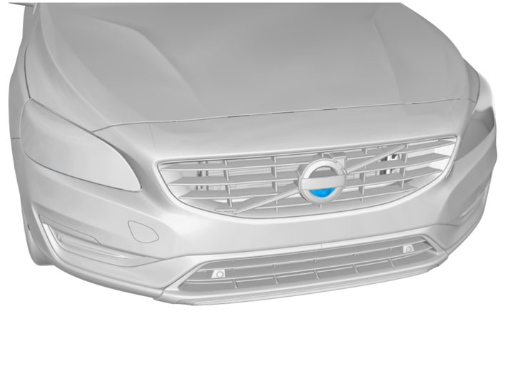
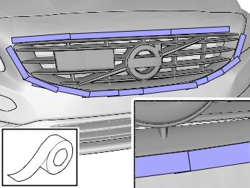
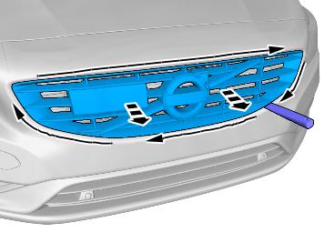
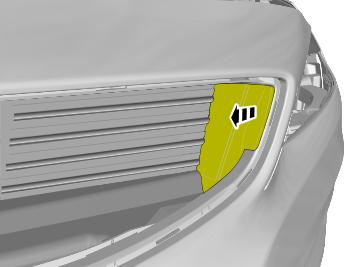
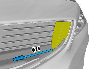
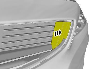
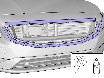
| | Place the tape so that it enters under the grille edge, protecting the painted area when removing the grille. Use: , Electrical tape
|
|  | | IMG-385038 |
|
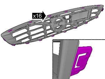
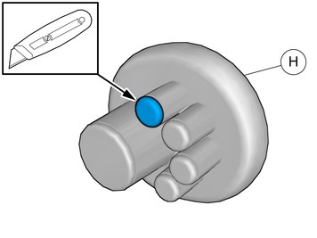
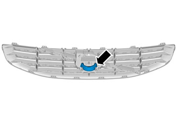
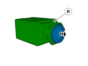
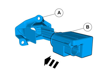
| | Note!
The graphic shows the back of the component before removal. |
|
|  | | IMG-385133 |
|
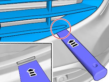
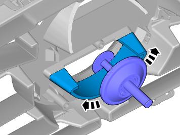
| |
Use special tool: T9997390, Key
|
|  | | IMG-385134 |
|
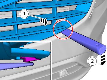
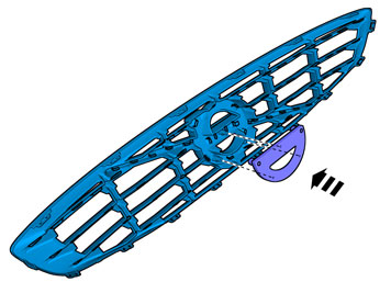
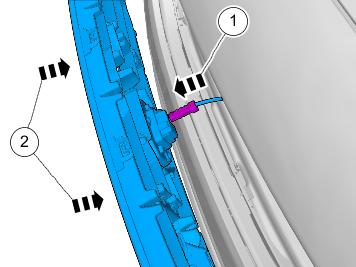
| | Pull the grille outwards with one hand and keep it there while undoing the next retainer hook. |
|  | | IMG-385135 |
|
| | |
|  | | IMG-385487 |
|
| | |
|  | | IMG-385492 |
|
| | |
|  | | IMG-385055 |
|
| | |
|  | | IMG-385588 |
|
| | |
| | |
|  | | IMG-385591 |
|
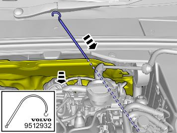
| | Fold the insulation aside.
Use special tool: T9512932, Tension spring
|
|  | | IMG-382096 |
|
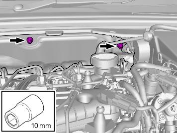
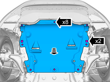
| | Raise the car. Remove the clips. Remove the screws. |
|  | | IMG-382097 |
|
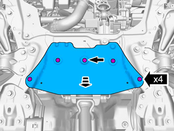
| | Remove the clip. Remove the screws. |
|  | | IMG-385520 |
|
| | |
|  | | IMG-385183 |
|
| | |
|  | | IMG-353681 |
|
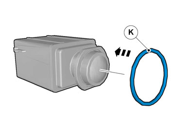
| | Use: Expander pliers
Use: 1161427, Low temperature grease
|
|  | | IMG-385545 |
|
| | Caution!
Make sure that the rubber grommet seals properly to the body. |
|
|  | | IMG-385553 |
|
| | |
|  | | IMG-385554 |
|
| | |
|  | | IMG-385596 |
|
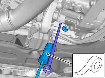
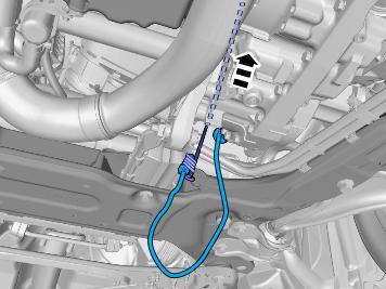
| | Pull the wiring through. Remove the Special Tool. |
|  | | IMG-385728 |
|
| | |
|  | | IMG-385819 |
|
| | |
|  | | IMG-385719 |
|
| | |
|  | | IMG-385736 |
|
| | |
|  | | IMG-385746 |
|
| | |
|  | | IMG-385816 |
|
| | |
|  | | IMG-385818 |
|
| | |
|  | | IMG-385825 |
|
| | |
|  | | IMG-385837 |
|
| | |
|  | | IMG-385826 |
|
| | |
|  | | IMG-385368 |
|
| | |
|  | | IMG-385977 |
|
| | |
|  | | IMG-385918 |
|
| | |
|  | | IMG-385324 |
|
| | Remove the tape. Remove any traces of glue. Use: , Isopropanol
|
|  | | IMG-375758 |
|
| | Caution!
Place the component on a suitable underlay or support. |
|
|  | | IMG-385394 |
|
| | Note!
This step is easier with two people. |
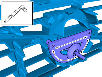
Use: Angle drill machine
Use special tool: T9997482, Cutting tool
|
|  | | IMG-375795 |
|
| |
Use special tool: T9997482, Cutting tool
|
|  | | IMG-375753 |
|
| | Use: Angle drill machine
Use special tool: T9997482, Cutting tool
|
|  | | IMG-375800 |
|
| | |
|  | | IMG-347781 |
|
| | |
|  | | IMG-347786 |
|
| | |
|  | | IMG-374396 |
|
| | |
|  | | IMG-374391 |
|
| | |
|  | | IMG-385430 |
|
| | Connect the connector. Reinstall the removed part. |
| | | IMG-377070 |
|
| | Reinstall the removed parts in reverse order. |
|  | | IMG-242268 |
|
| | Download software (application) for the accessory's function according to the service information in VIDA. Order and download software according to: 31285245
|