| | |
| | Read through all of the instructions before starting installation. Notifications and warning texts are for your safety and to minimise the risk of something breaking during installation. Ensure that all tools stated in the instructions are available before starting installation. Certain steps in the instructions are only presented in the form of images. Explanatory text is also given for more complicated steps. In the event of any problems with the instructions or the accessory, contact your local Volvo dealer.
|
| | |
|  | | IMG-400007 |
|
| | Note!
If a pending accessories installation include the removing and replacing of the bumper, this installation should be carried out first. |
When installing, the car must retain a temperature of 20 degrees C. After installation, the car must not be washed for 48 hours |
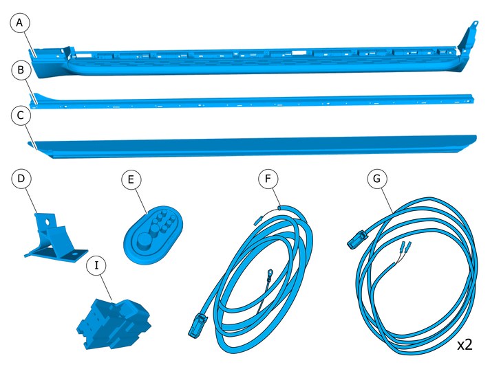
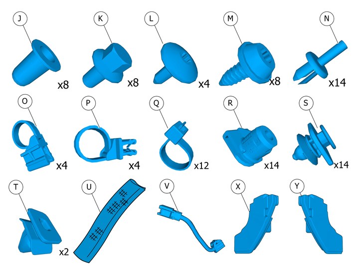
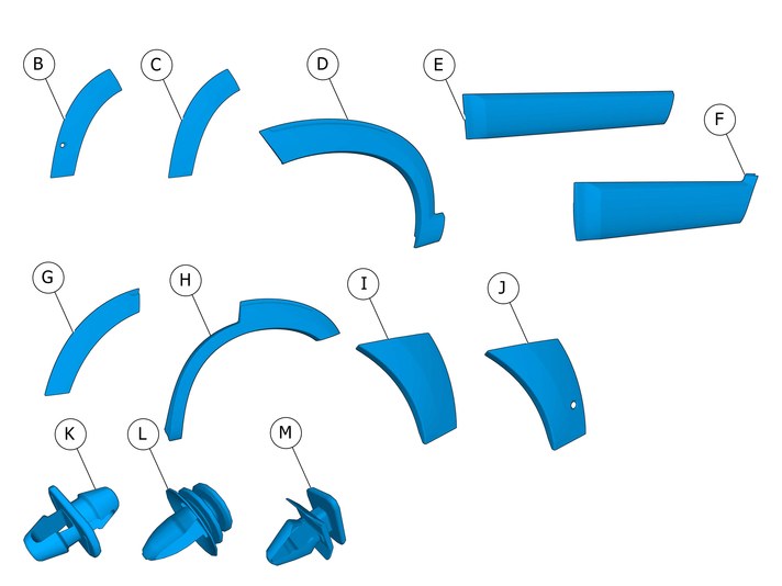
| | There may be parts in the accessories kit that are not needed for this installation. |
| | | IMG-400007 |
|
| | Vehicles without pre-routed wiring harness (variant code 2901) Vehicles with pre-routed wiring harness (variant code 2902) |
| | |
|  | | IMG-363036 |
|
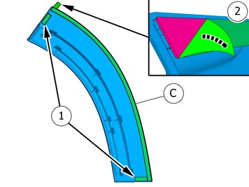
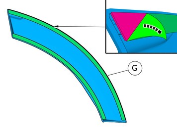
| | Note!
This colour chart displays (in colour print and electronic version) the importance of the different colours used in the images of the method steps. |
Used for focused component, the component with which you will do something. Used as extra colors when you need to show or differentiate additional parts. Used for attachments that are to be removed/installed. May be screws, clips, connectors, etc. Used when the component is not fully removed from the vehicle but only hung to the side. Used for standard tools and special tools. Used as background color for vehicle components.
|
| | Vehicles with Parking assistance pilot |
|  | | IMG-407652 |
|
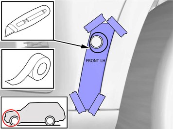
| | Print templates from Service Product Journal (SPJ) 30519 |
|  | | IMG-407831 |
|
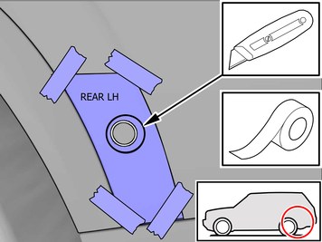
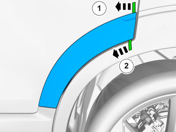
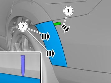
| | Secure the template with tape. Scribe/mark up Remove the tape.
Repeat on the other side. |
|  | | IMG-407851 |
|
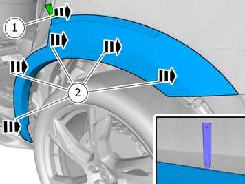
| | Secure the template with tape. Scribe/mark up Remove the tape.
Repeat on the other side. |
| | |
| | Disconnecting the battery |
|  | | IMG-394535 |
|
| | |
|  | | IMG-394779 |
|
| | |
|  | | IMG-387004 |
|
| | |
|  | | IMG-394520 |
|
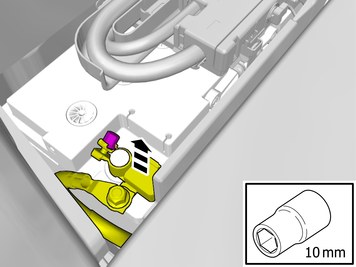
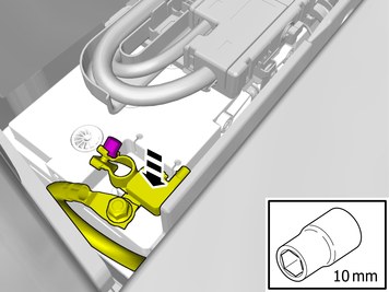
| | Remove the battery's negative cable. |
| | |
|  | | IMG-382894 |
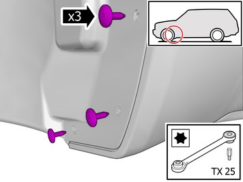
|
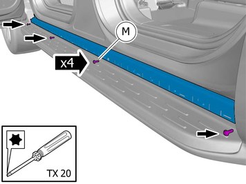
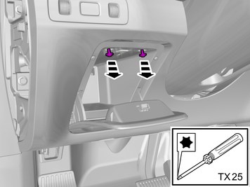
| | Note!
The screws are to be reused. |
Remove the screws. |
|  | | IMG-382895 |
|
| | Note!
The screws are to be reused. |
Remove the screws. |
|  | | IMG-393050 |
|
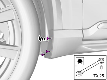
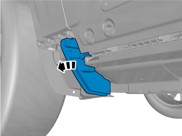
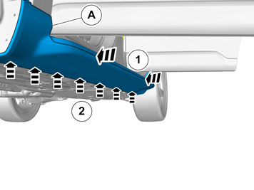
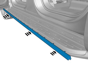
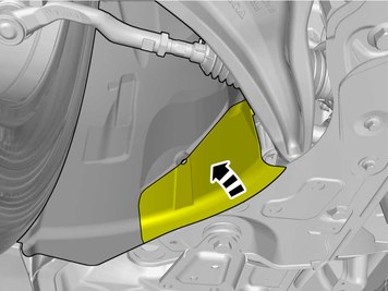
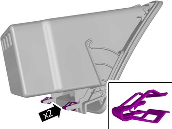
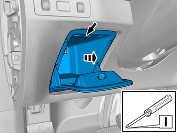
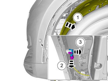
| | Remove the marked part. The part is not to be reused. |
|  | | IMG-393051 |
|
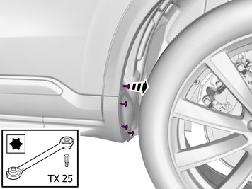
| | Remove the marked part. The part is not to be reused. |
|  | | IMG-393060 |
|
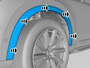
| | Remove the marked part. The part is not to be reused. |
|  | | IMG-393062 |
|
| | Remove the marked part. The part is not to be reused. |
|  | | IMG-382898 |
|
| | |
|  | | IMG-382932 |
|
| | Remove the marked part. The part is not to be reused. |
|  | | IMG-401092 |
|
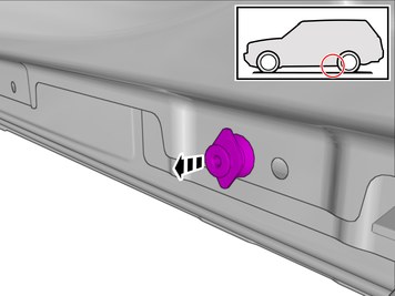
| | The part is not to be reused. |
|  | | IMG-382998 |
|
| | Caution!
The part is to be reused. |
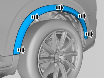
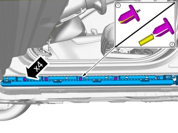
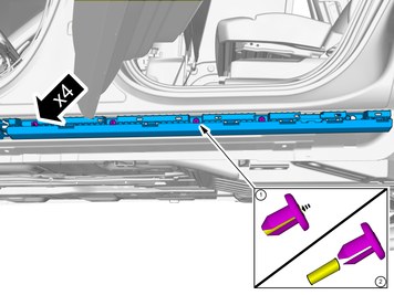
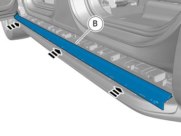
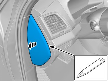
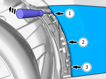
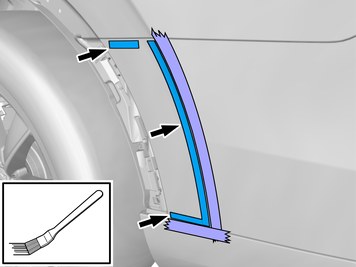
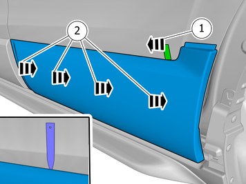
Loosen the clips. Remove the weatherstrip. |
|  | | IMG-382930 |
|
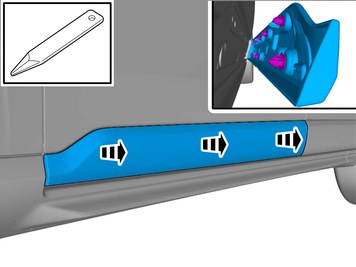
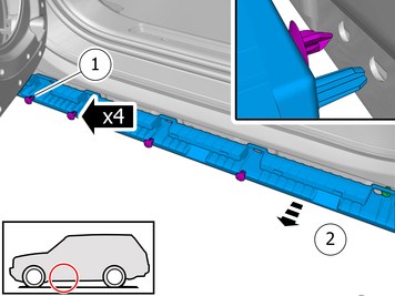
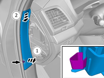
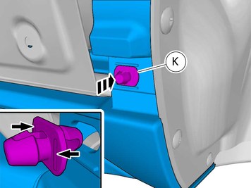
| | Loosen the clips. Use: Drift
|
|  | | IMG-387609 |
|
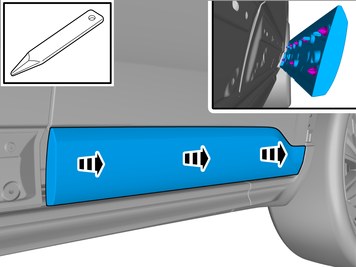
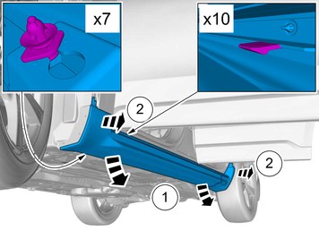
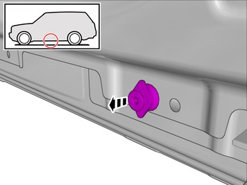
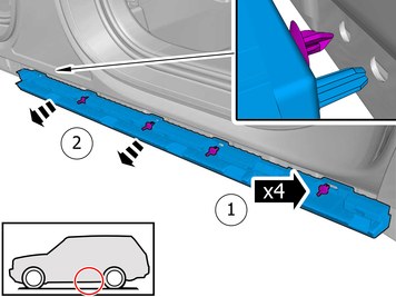
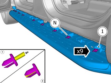
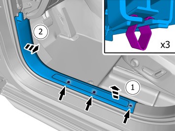
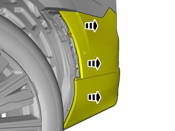
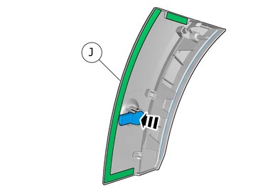
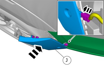
| | Remove the clips. Remove the panel.
The part is not to be reused. |
|  | | IMG-387618 |
|
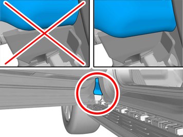
| | Note!
Make sure that the mating faces are clean and free of foreign material. |
|
|  | | IMG-382933 |
|
| | Loosen the clips. Use: Drift
|
|  | | IMG-397600 |
|
| | Remove the clips. Remove the panel.
The part is not to be reused. |
|  | | IMG-388413 |
|
| | Note!
Make sure that the mating faces are clean and free of foreign material. |
|
|  | | IMG-408475 |
|
| | Note!
Make sure that the mating faces are clean and free of foreign material. |
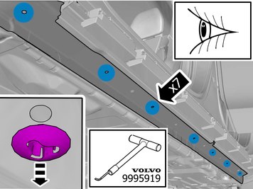
Remove the marked part.
Use special tool: T9995919, PULLER (SEAL-PINION,CAM-CRANKSHAFT)B200-6304
|
| | |
|  | | IMG-393237 |
|
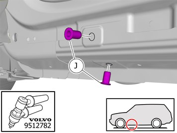
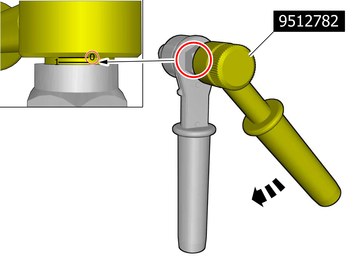
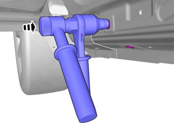
| |
Use special tool: T9512782, Rivet nut tool
|
|  | | IMG-393238 |
|
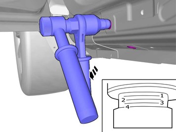
| |
Use special tool: T9512782, Rivet nut tool
|
|  | | IMG-372305 |
|
| | |
|  | | IMG-397692 |
|
| | |
|  | | IMG-367098 |
|
| | |
|  | | IMG-397605 |
|
| | |
|  | | IMG-397670 |
|
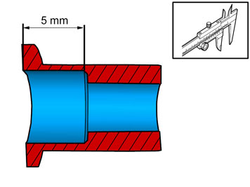
| | Tighten to the value stated. |
|  | | IMG-373060 |
|
| | |
|  | | IMG-393239 |
|
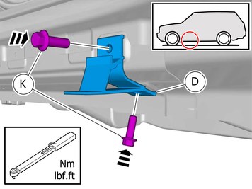
| | Install the screws.
Tightening torque: M10
, 50 Nm
|
|  | | IMG-393240 |
|
| | Install the screws.
Tightening torque: M10
, 50 Nm
|
|  | | IMG-382940 |
|
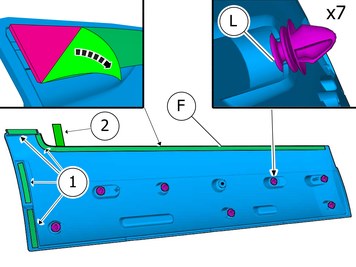
| | Install component that comes with the accessory kit. |
|  | | IMG-387358 |
|
| | |
|  | | IMG-382942 |
|
| | |
|  | | IMG-393242 |
|
| | Install component that comes with the accessory kit. Install the screws.
Tightening torque: M8
, 24 Nm
|
|  | | IMG-427210 |
|
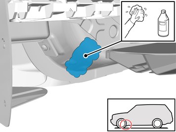
| | Clean the surface. Use: 1161721, Isopropanol
Wipe dry. |
|  | | IMG-433909 |
|
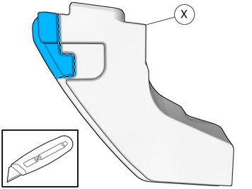
| | Caution!
Cut carefully to avoid unintentional damage or personal injury. |
Remove the marked part. |
|  | | IMG-427220 |
|
| | Remove the protective film. |
|  | | IMG-433914 |
|
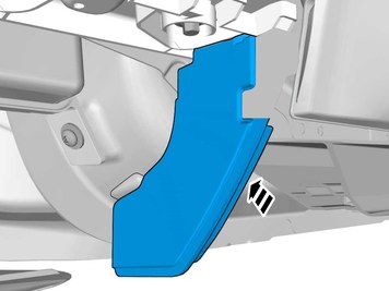
| | Note!
Ensure that the tape is fixed to the surface. |
Install the marked component. |
|  | | IMG-393243 |
|
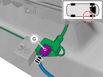
| | Install component that comes with the accessory kit. Connect the cable harness. |
|  | | IMG-393270 |
|
| | Install component that comes with the accessory kit. Connect the cable harness. |
|  | | IMG-394058 |
|
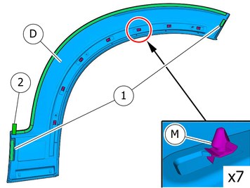
| | Install component that comes with the accessory kit. Install the clip(s). |
|  | | IMG-394036 |
|
| | Install component that comes with the accessory kit. Install the clip(s). |
|  | | IMG-394057 |
|
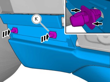
| | Install component that comes with the accessory kit. Install the clip(s). |
|  | | IMG-382982 |
|
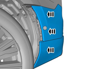
| | Note!
This step is easier with two people. |
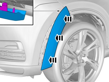
Install component that comes with the accessory kit. Use hands only. Ensure that all clips engage. |
|  | | IMG-397622 |
|
| | |
|  | | IMG-411833 |
|
| | |
|  | | IMG-397623 |
|
| | Install component that comes with the accessory kit. |
|  | | IMG-397630 |
|
| | |
|  | | IMG-397634 |
|
| | Reinstall the weatherstrip. |
|  | | IMG-404590 |
|
| | |
| | |
|  | | IMG-397625 |
|
| | |
|  | | IMG-397632 |
|
| | |
| | Repeat the steps when removing on opposite side. Repeat the steps when installing accessories on opposite side. |
| | |
|  | | IMG-404418 |
|
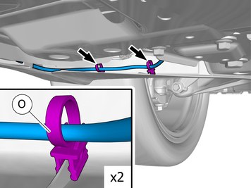
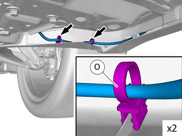
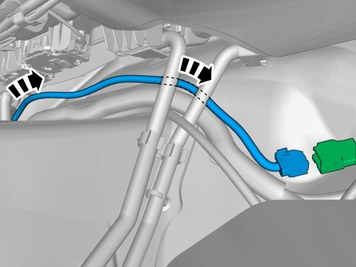
| | Position/route the cable harness as illustrated. Install the clips as illustrated. Tighten the cable ties. |
|  | | IMG-404419 |
|
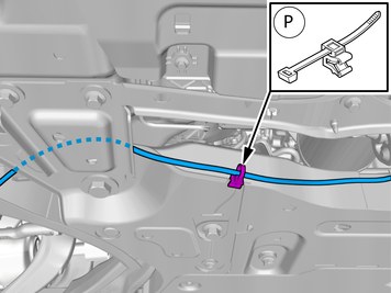
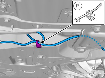
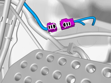
| | Position/route the cable harness as illustrated. Install the clip(s). Tighten the cable tie. |
|  | | IMG-401385 |
|
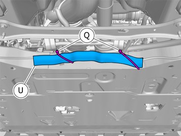
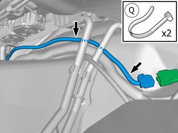
| | Caution!
Make sure to locate the wiring in such a way that any damage caused by heat or excessive wear is avoided. |
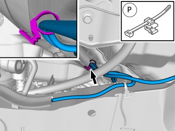
Install component that comes with the accessory kit. Tighten the cable ties. |
|  | | IMG-404424 |
|
| | Position/route the cable harness as illustrated. Install the clips as illustrated. Tighten the cable ties. |
|  | | IMG-404427 |
|
| | Position/route the cable harness as illustrated. Install the clip(s). Tighten the cable tie. |
|  | | IMG-404431 |
|
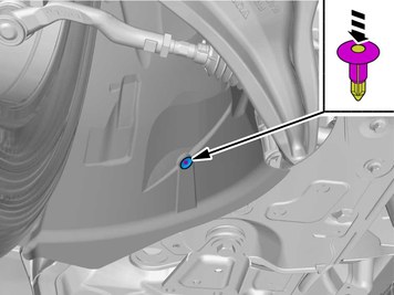
| | Install the clip(s). Tighten the cable tie. |
| | |
|  | | IMG-404385 |
|
| | |
|  | | IMG-404387 |
|
| | |
|  | | IMG-386950 |
|
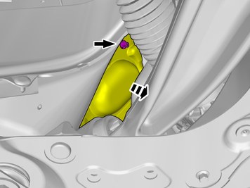
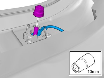
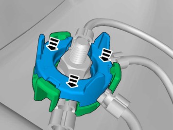
| | Remove the nut. Fold the insulation aside. |
|  | | IMG-386951 |
|
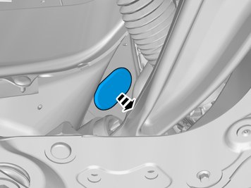
| | Remove the marked part. The part is not to be reused. |
|  | | IMG-402286 |
|
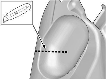
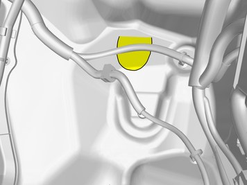
| | Make a cut in the insulation. |
|  | | IMG-390109 |
|
| | Remove the panel. Disconnect the connector, if applicable. |
|  | | IMG-390116 |
|
| | |
|  | | IMG-390091 |
|
| | Disconnect the connector, if applicable. |
|  | | IMG-390106 |
|
| | |
|  | | IMG-386974 |
|
| | |
|  | | IMG-386994 |
|
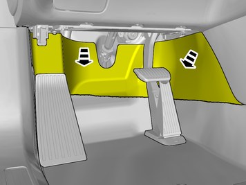
| | Fold the insulation aside. |
| | |
|  | | IMG-393255 |
|
| | |
|  | | IMG-391525 |
|
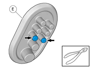
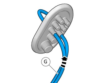
| | Pull the wiring through. Use: 1161150, Lubricant
|
|  | | IMG-404391 |
|
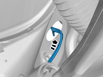
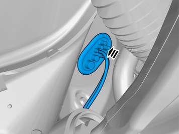
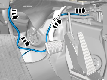
| | Route the wiring harness into the passenger compartment. |
|  | | IMG-404405 |
|
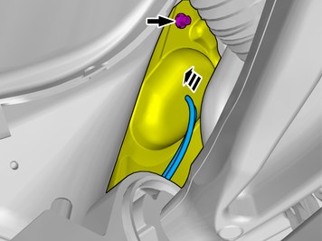
| | Caution!
Make sure that the rubber grommet seals properly to the body. |
Insert the cable in to the passenger compartment, adjust the cable length out into the engine compartment and secure the rubber grommet. |
| | |
|  | | IMG-404406 |
|
| | Refit the insulation. Install the nut. |
| | | IMG-404385 |
|
| | Reinstall the removed part. |
| | |
|  | | IMG-404520 |
|
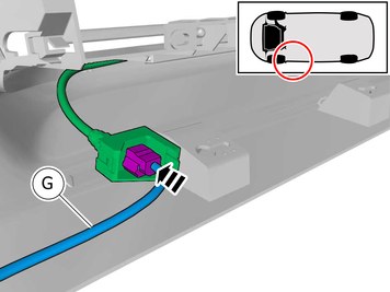
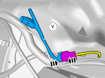
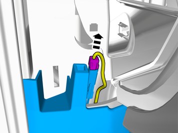
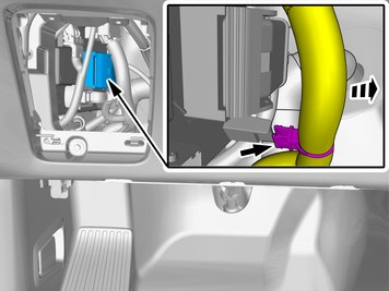
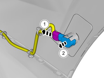
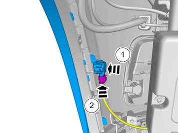
| | Note the position. Connect the cable harness. |
|  | | IMG-404540 |
|
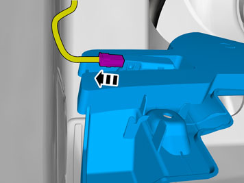
| | Depress the secondary lock. |
|  | | IMG-404462 |
|
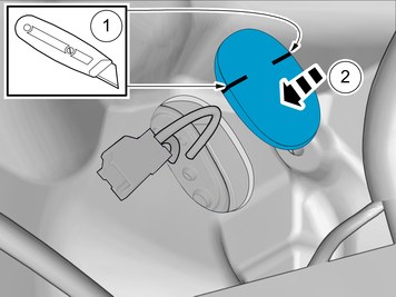
| | Note!
This step is only necessary if the component in the graphic is included in the accessory kit. |
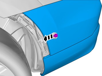
Connect the connector. |
|  | | IMG-387934 |
|
| | Make a cut in the insulation. Refit the insulation.
|
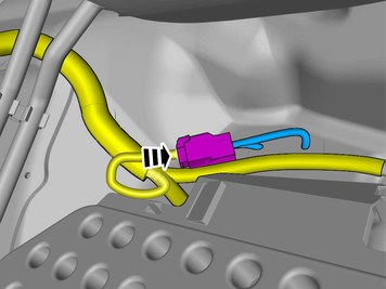
| | Vehicles with pre-routed wiring harness (variant code 2902) |
|  | | IMG-396505 |
|
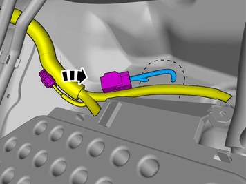
| | Locate the existing connector in the vehicle's cable harness. |
|  | | IMG-396523 |
|
| | |
| | Vehicles without pre-routed wiring harness (variant code 2901) |
|  | | IMG-404505 |
|
| | |
| | |
|  | | IMG-398045 |
|
| | |
|  | | IMG-398044 |
|
| | |
|  | | IMG-398043 |
|
| | |
|  | | IMG-398030 |
|
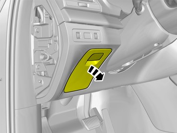
| | Disconnect the connector, if applicable. |
|  | | IMG-383314 |
|
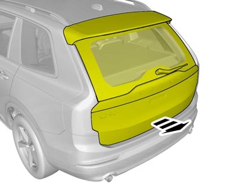
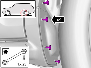
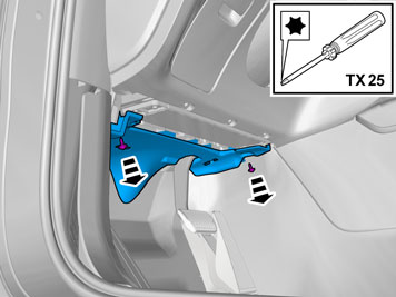
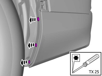
| | Remove the screws. Detach the panel. |
|  | | IMG-383315 |
|
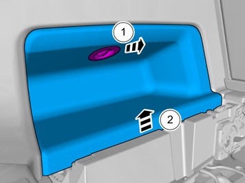
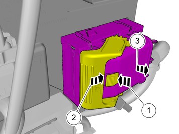
| | Disconnect the connector. Remove the panel. |
|  | | IMG-387085 |
|
| | |
|  | | IMG-387086 |
|
| | |
|  | | IMG-403400 |
|
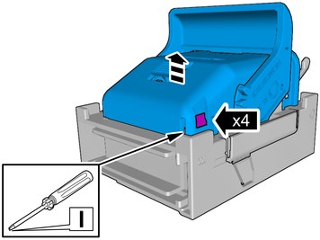
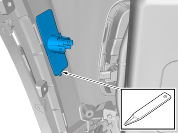
| | Note!
The graphic shows the back of the component before removal. |
|
|  | | IMG-387107 |
|
| | |
|  | | IMG-407635 |
|
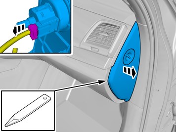
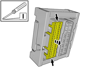
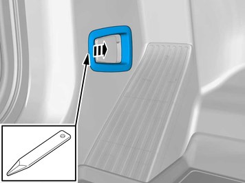
| | Loosen the clip. Fold marked part aside. |
|  | | IMG-387415 |
|
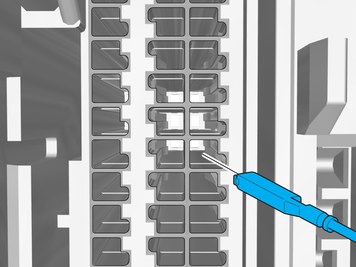
| | Depress the locking device. Release the connector's catch. Disconnect the connector.
|
|  | | IMG-387423 |
|
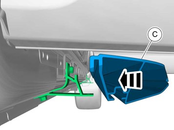
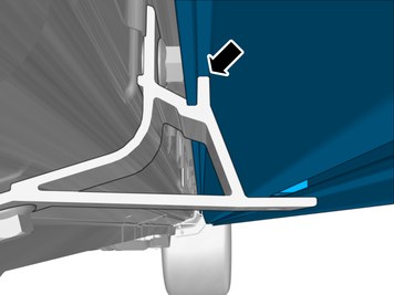
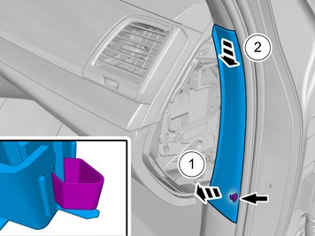
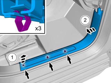
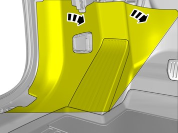
| | Release the catches. Remove the marked part. |
|  | | IMG-456395 |
|
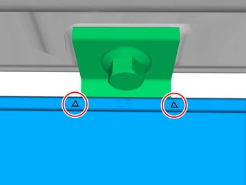
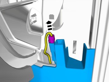
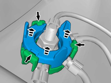
| | Release the connector's secondary lock. Lift approximately 2 mm. |
| | |
|  | | IMG-456396 |
|
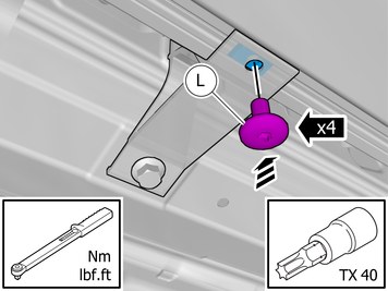
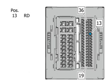
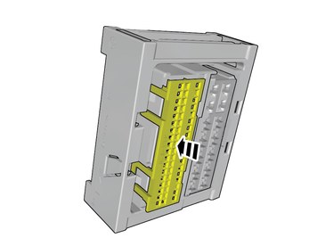
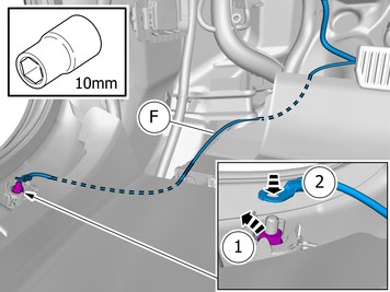
| | Connect the prerouted wiring harness. Connect the cable harness terminals in the connector as follows. |
|  | | IMG-387465 |
|
| | |
|  | | IMG-456400 |
|
| | Depress the secondary lock. |
|  | | IMG-387424 |
|
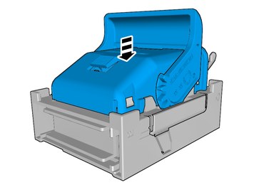
| | Reinstall the removed part. |
|  | | IMG-393020 |
|
| | |
|  | | IMG-388280 |
|
| | |
|  | | IMG-388299 |
|
| | |
|  | | IMG-397643 |
|
| | Release the catches. Remove the marked part. |
|  | | IMG-393258 |
|
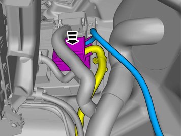
| | Ground connection Remove the nut. Connect the cable.
|
|  | | IMG-388368 |
|
| | Install the nut.
Tightening torque: M6
, 10 Nm
|
|  | | IMG-397646 |
|
| | Reinstall the removed part. |
|  | | IMG-386826 |
|
| | |
|  | | IMG-387783 |
|
| | Position/route the cable harness as illustrated. Route the wire adjacent to existing wirings. |
|  | | IMG-404490 |
|
| | Install the wiring harness. Use a cable tie |
|  | | IMG-387776 |
|
| | Position/route the cable harness as illustrated. Route the wire adjacent to existing wirings. |
|  | | IMG-385213 |
|
| | |
|  | | IMG-404491 |
|
| | Install the wiring harness. Use a cable tie Attach any excess wire to the wiring harness. |
| | |
| | Reinstall the removed parts in reverse order. |
| | Vehicles with Parking assistance pilot |
| | |
|  | | IMG-383588 |
|
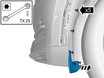
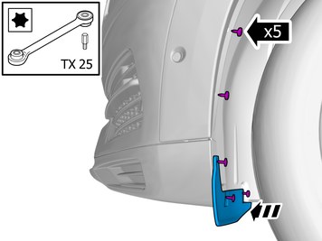
| | Remove the screws. Remove the marked part. |
|  | | IMG-383613 |
|
| | Fold the wing liner aside. Disconnect the connector. Remove the part carefully The part is to be reused. |
|  | | IMG-383638 |
|
| | |
|  | | IMG-407875 |
|
| | Remove the marked part. Use: Air-powered air saw
|
|  | | IMG-393176 |
|
| | |
|  | | IMG-401258 |
|
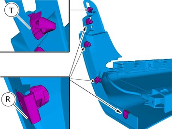
| | Release the catches. Remove the part carefully |
|  | | IMG-393178 |
|
| | |
|  | | IMG-383440 |
|
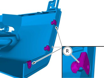
| | Disconnect the connector. Remove the marked part. |
|  | | IMG-393180 |
|
| | |
|  | | IMG-407926 |
|
| | Remove the marked part. Use: Air-powered air saw
|
| | |
|  | | IMG-383483 |
|
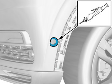
| | Locate the connector. Pull the wiring through. |
|  | | IMG-393179 |
|
| | |
|  | | IMG-393177 |
|
| | |
| | |
| | |
|  | | IMG-393275 |
|
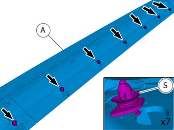
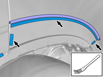
| | Install component that comes with the accessory kit. Install the clips as illustrated. |
|  | | IMG-394588 |
|
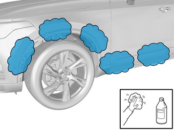
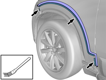
| | Clean the surfaces. Use: 1161721, Cleaning agent
|
|  | | IMG-394598 |
|
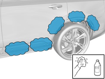
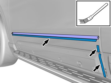
| | Clean the surfaces. Use: 1161721, Cleaning agent
|
|  | | IMG-397767 |
|
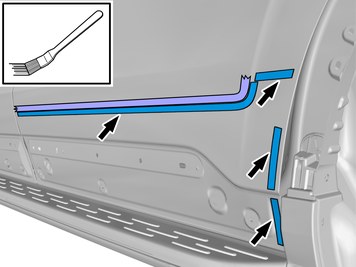
| | Clean the surface. Use: 1161721, Cleaning agent
|
|  | | IMG-425420 |
|
| | Note!
This step is easier with two people. |
Hold the component in the position shown. Use: Masking tape
Remove the marked part. |
|  | | IMG-425422 |
|
| | Note!
This step is easier with two people. |
Hold the component in the position shown. Use: Masking tape
Remove the marked part. |
|  | | IMG-425426 |
|
| | Note!
This step is easier with two people. |
Hold the component in the position shown. Use: Masking tape
Remove the marked part. |
|  | | IMG-425448 |
|
| | Note!
This step is easier with two people. |
Hold the component in the position shown. Use: Masking tape
Remove the marked part. |
|  | | IMG-425450 |
|
| | Note!
This step is easier with two people. |
Hold the component in the position shown. Use: Masking tape
Remove the marked part. |
|  | | IMG-425466 |
|
| | Note!
This step is easier with two people. |
Hold the component in the position shown. Use: Masking tape
Remove the marked part. |
|  | | IMG-425467 |
|
| | Note!
This step is easier with two people. |
Hold the component in the position shown. Use: Masking tape
Remove the marked part. |
|  | | IMG-425290 |
|
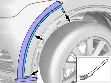
| | Apply a thin layer of primer. Allow to dry for at least 5 minutes but not more than 30 minutes. Use: 1161727, Primer
Remove the tape. |
|  | | IMG-425292 |
|
| | Apply a thin layer of primer. Allow to dry for at least 5 minutes but not more than 30 minutes. Use: 1161727, Primer
Remove the tape. |
|  | | IMG-425485 |
|
| | Apply a thin layer of primer. Allow to dry for at least 5 minutes but not more than 30 minutes. Use: 1161727, Primer
Remove the tape. |
|  | | IMG-425486 |
|
| | Apply a thin layer of primer. Allow to dry for at least 5 minutes but not more than 30 minutes. Use: 1161727, Primer
Remove the tape. |
|  | | IMG-425296 |
|
| | Apply a thin layer of primer. Allow to dry for at least 5 minutes but not more than 30 minutes. Use: 1161727, Primer
Remove the tape. |
|  | | IMG-425294 |
|
| | Apply a thin layer of primer. Allow to dry for at least 5 minutes but not more than 30 minutes. Use: 1161727, Primer
Remove the tape. |
|  | | IMG-425297 |
|
| | Apply a thin layer of primer. Allow to dry for at least 5 minutes but not more than 30 minutes. Use: 1161727, Primer
Remove the tape. |
|  | | IMG-393283 |
|
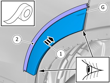
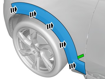
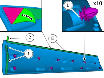
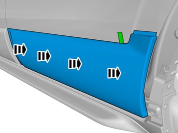
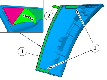
| | Install component that comes with the accessory kit. Remove the protective film. Fold the protective film forward
|
|  | | IMG-393310 |
|
| | |
|  | | IMG-393286 |
|
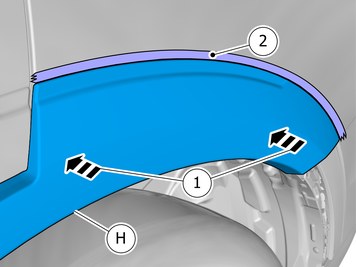
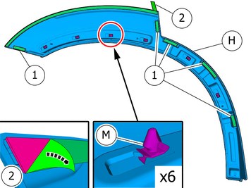
| | Install component that comes with the accessory kit. Install the clip(s). Remove the protective film. Fold the protective film forward
|
|  | | IMG-400452 |
|
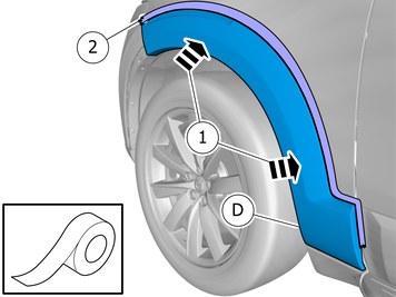
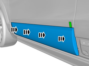
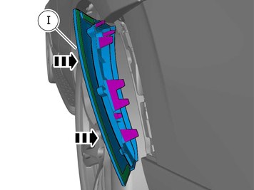
| | Ensure that all clips engage. |
|  | | IMG-400362 |
|
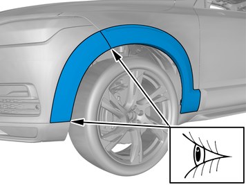
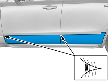
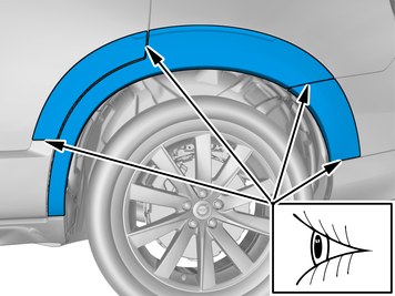
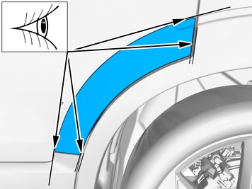
| | Note!
Adjust the position of the components to create even spaces. |
|
|  | | IMG-393285 |
|
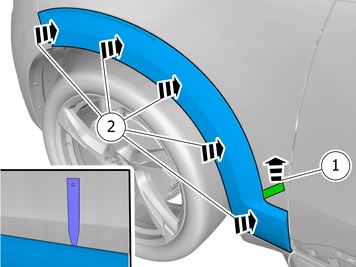
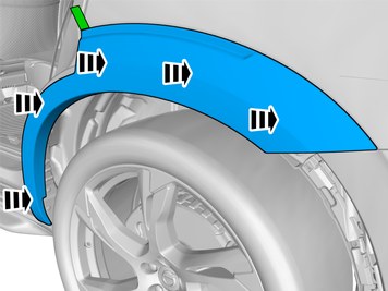
| | Note!
Apply a pressure of 35 - 50 N/cm2 for 2-3 seconds. This corresponds to a thumb pressure of 3.5 - 5 kg - test with scales first. If the palm of a hand or an application roller is used, remember that the larger surface requires greater force. |
Ensure that all clips engage. Remove the protective film. Hint
Press and apply pressure to the part over the tape for at least 20 seconds. |
|
|  | | IMG-397752 |
|
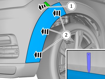
| | Note!
Apply a pressure of 35 - 50 N/cm2 for 2-3 seconds. This corresponds to a thumb pressure of 3.5 - 5 kg - test with scales first. If the palm of a hand or an application roller is used, remember that the larger surface requires greater force. |
Remove the protective film. Hint
Press and apply pressure to the part over the tape for at least 20 seconds. |
|
| | Vehicles with Parking assistance pilot |
| | |
|  | | IMG-383720 |
|
| | Locate the pre-routed connector. Reinstall the removed part. Connect the connector. |
|  | | IMG-383721 |
|
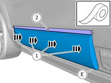
| | Reinstall the removed part. Reinstall the screws. |
| | |
| | |
|  | | IMG-393287 |
|
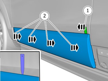
| | Install component that comes with the accessory kit. Install the clip(s). Remove the protective film. Fold the protective film forward
|
|  | | IMG-393294 |
|
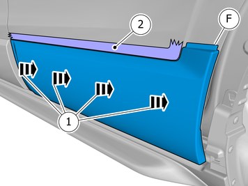
| | Ensure that all clips engage. |
|  | | IMG-393290 |
|
| | Install component that comes with the accessory kit. Install the clip(s). Remove the protective film. Fold the protective film forward
|
|  | | IMG-393297 |
|
| | Ensure that all clips engage. |
|  | | IMG-400995 |
|
| | Note!
Adjust the position of the components to create even spaces. |
Adjust the component to a horizontal position. |
|  | | IMG-400999 |
|
| | Note!
Apply a pressure of 35 - 50 N/cm2 for 2-3 seconds. This corresponds to a thumb pressure of 3.5 - 5 kg - test with scales first. If the palm of a hand or an application roller is used, remember that the larger surface requires greater force. |
Remove the protective film. Hint
Press and apply pressure to the part over the tape for at least 20 seconds. |
Hint
To ease removal of the protective film, use interior trim remover tool to lift the component just a bit. |
|
|  | | IMG-401000 |
|
| | Note!
Apply a pressure of 35 - 50 N/cm2 for 2-3 seconds. This corresponds to a thumb pressure of 3.5 - 5 kg - test with scales first. If the palm of a hand or an application roller is used, remember that the larger surface requires greater force. |
Remove the protective film. Hint
Press and apply pressure to the part over the tape for at least 20 seconds. |
Hint
To ease removal of the protective film, use interior trim remover tool to lift the component just a bit. |
|
|  | | IMG-393284 |
|
| | Install component that comes with the accessory kit. Install the clips as illustrated. |
| | Vehicles with Parking assistance pilot |
|  | | IMG-393299 |
|
| | Reinstall the removed part. |
|  | | IMG-393301 |
|
| | |
| | |
|  | | IMG-393295 |
|
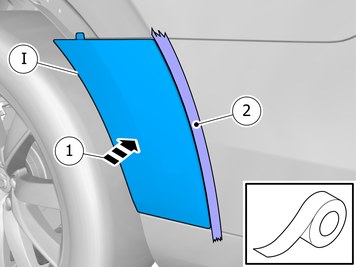
| | Install component that comes with the accessory kit. Remove the protective film. Fold the protective film forward
|
|  | | IMG-393296 |
|
| | Install component that comes with the accessory kit. |
|  | | IMG-393190 |
|
| | |
|  | | IMG-393292 |
|
| | Install component that comes with the accessory kit. Install the clip(s). Remove the protective film. Fold the protective film forward
|
|  | | IMG-400451 |
|
| | Ensure that all clips engage. |
|  | | IMG-393192 |
|
| | |
|  | | IMG-393293 |
|
| | Install component that comes with the accessory kit. Fold the protective film forward |
|  | | IMG-400356 |
|
| | Note!
Adjust the position of the components to create even spaces. |
|
|  | | IMG-400627 |
|
| | Note!
Adjust the position of the components to create even spaces. |
|
|  | | IMG-383384 |
|
| | Note!
Apply a pressure of 35 - 50 N/cm2 for 2-3 seconds. This corresponds to a thumb pressure of 3.5 - 5 kg - test with scales first. If the palm of a hand or an application roller is used, remember that the larger surface requires greater force. |
Remove the protective film. Hint
Press and apply pressure to the part over the tape for at least 20 seconds. |
|
|  | | IMG-393298 |
|
| | Note!
Apply a pressure of 35 - 50 N/cm2 for 2-3 seconds. This corresponds to a thumb pressure of 3.5 - 5 kg - test with scales first. If the palm of a hand or an application roller is used, remember that the larger surface requires greater force. |
Remove the protective film. Hint
Press and apply pressure to the part over the tape for at least 20 seconds. |
Hint
To ease removal of the protective film, use interior trim remover tool to lift the component just a bit. |
|
|  | | IMG-397760 |
|
| | Note!
Apply a pressure of 35 - 50 N/cm2 for 2-3 seconds. This corresponds to a thumb pressure of 3.5 - 5 kg - test with scales first. If the palm of a hand or an application roller is used, remember that the larger surface requires greater force. |
Remove the protective film. Hint
Press and apply pressure to the part over the tape for at least 20 seconds. |
Hint
To ease removal of the protective film, use interior trim remover tool to lift the component just a bit. |
|
| | Repeat all method steps for the other side. |
| | |
|  | | IMG-394580 |
|
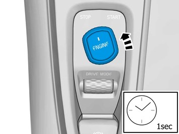
| | Reinstall the battery's negative cable.
Tightening torque: Battery cable for battery
, 6 Nm
|
| | |
| | Reinstall the removed parts in reverse order. |
|  | | IMG-401100 |
|
| | Note!
Make sure that the component is clean and free of foreign material. |
|
|  | | IMG-242268 |
|
| | Download software (application) for the accessory's function according to the service information in VIDA. Order and download software according to: 31414888
|