| | |
| | Read through all of the instructions before starting installation. Notifications and warning texts are for your safety and to minimise the risk of something breaking during installation. Ensure that all tools stated in the instructions are available before starting installation. Certain steps in the instructions are only presented in the form of images. Explanatory text is also given for more complicated steps. In the event of any problems with the instructions or the accessory, contact your local Volvo dealer.
|
| | |
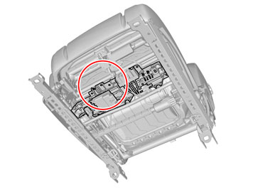
|  | | IMG-363036 |
|
| | Note!
This colour chart displays (in colour print and electronic version) the importance of the different colours used in the images of the method steps. |
Used for focused component, the component with which you will do something. Used as extra colors when you need to show or differentiate additional parts. Used for attachments that are to be removed/installed. May be screws, clips, connectors, etc. Used when the component is not fully removed from the vehicle but only hung to the side. Used for standard tools and special tools. Used as background color for vehicle components.
|
| | |
|  | | IMG-332194 |
|
| | Set the ignition key to position I. |
|  | | IMG-292804 |
|
| | |
|  | | IMG-292806 |
|
| | |
|  | | IMG-292823 |
|
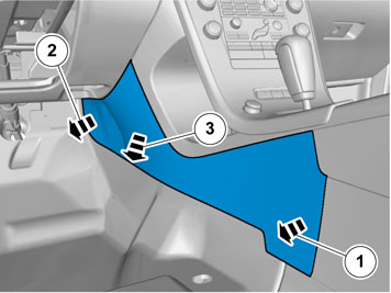
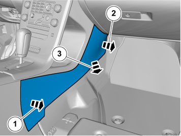
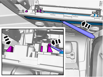
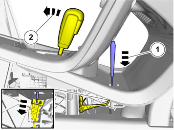
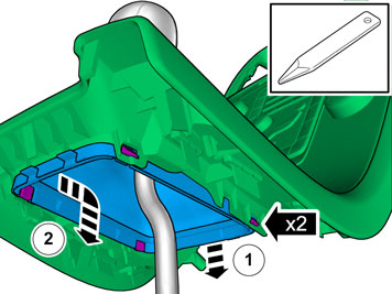
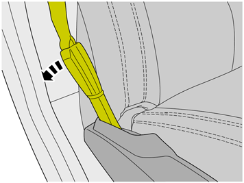
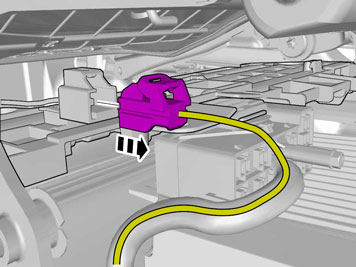
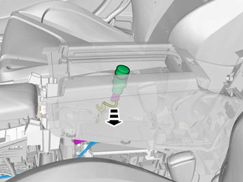
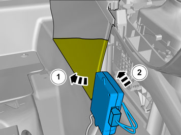
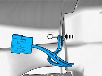
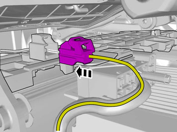
| | Unhook the cable harness clips. Disconnect the connector.
|
|  | | IMG-292826 |
|
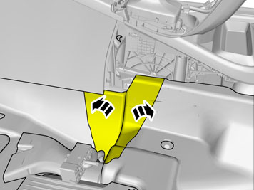
| | |
| | Vehicles with the 4C system. |
|  | | IMG-292827 |
|
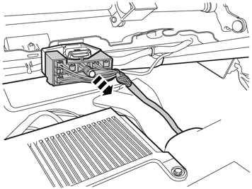
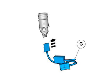
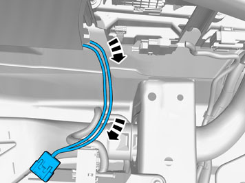
| | Disconnect the connector. |
| | |
|  | | IMG-345728 |
|
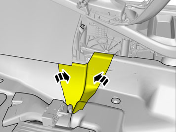
| | |
|  | | IMG-345734 |
|
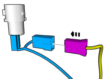
| | Disconnect the connector. |
|  | | IMG-292863 |
|
| | |
|  | | IMG-292883 |
|
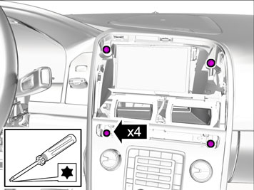
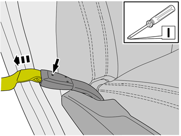
| | Use: Electrician's screwdriver
Repeat on the other side. |
|  | | IMG-345737 |
|
| | |
|  | | IMG-345744 |
|
| | |
|  | | IMG-345282 |
|
| | |
| | Cars with automatic transmissions |
|  | | IMG-345283 |
|
| | |
|  | | IMG-293007 |
|
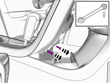
| | Release the shift-lock function. |
| | |
|  | | IMG-293009 |
|
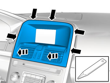
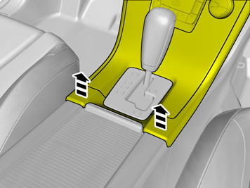
| | Detach the panel. Use hands only. |
|  | | IMG-371327 |
|
| | |
|  | | IMG-375925 |
|
| | |
| | Cars with manual transmissions |
|  | | IMG-345292 |
|
| | |
| | |
|  | | IMG-345290 |
|
| | |
| | Vehicles with the 4C system. |
|  | | IMG-345291 |
|
| | |
| | |
|  | | IMG-293021 |
|
| | |
|  | | IMG-293022 |
|
| | |
|  | | IMG-293023 |
|
| | |
|  | | IMG-371300 |
|
| | |
|  | | IMG-372558 |
|
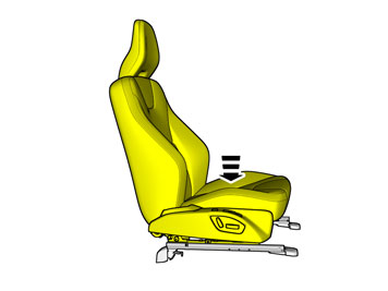
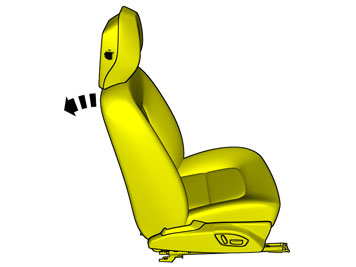
| | Adjust to the lowermost position. Repeat on the other side. |
|  | | IMG-372559 |
|
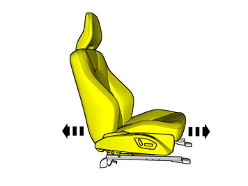
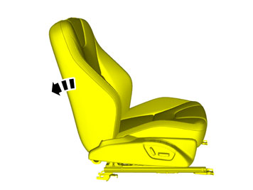
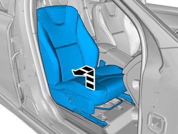
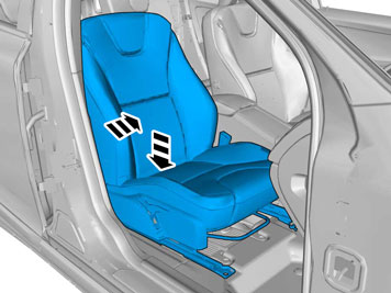
| | Adjust the seat to center position so that the seat fastening bolts can be removed. Repeat on the other side. |
|  | | IMG-332179 |
|
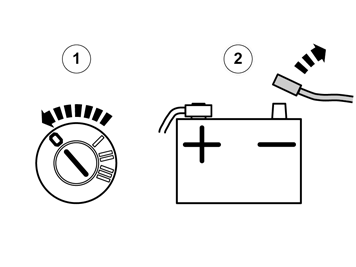
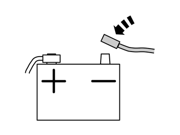
| | Set the ignition key to position 0. Remove the battery's negative cable.
|
|  | | IMG-329148 |
|
| | |
|  | | IMG-329150 |
|
| | |
|  | | IMG-340980 |
|
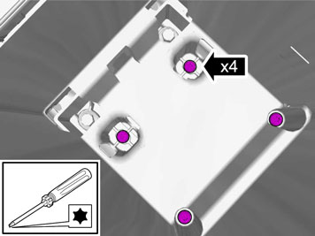
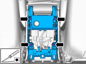
| | Remove the screws.
Tightening torque: Front seat to body
, 40 Nm
|
|  | | IMG-303005 |
|
| | |
|  | | IMG-303006 |
|
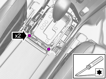
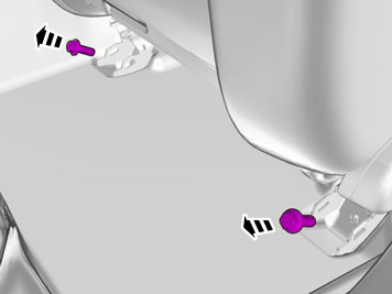
| | Remove the screws.
Tightening torque: Front seat to body
, 40 Nm
|
| | |
|  | | IMG-380657 |
|
| | |
| | |
|  | | IMG-380655 |
|
| | |
|  | | IMG-380656 |
|
| | |
| | |
|  | | IMG-329151 |
|
| | |
|  | | IMG-373198 |
|
| | |
|  | | IMG-382639 |
|
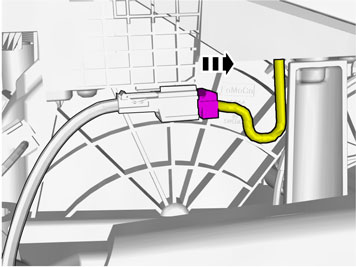
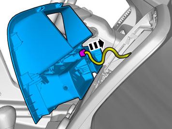
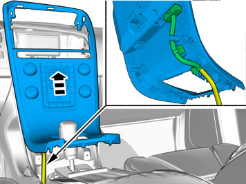
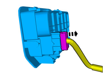
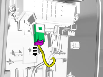
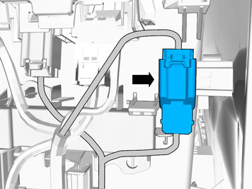
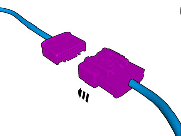
| | Disconnect the connector. |
|  | | IMG-329209 |
|
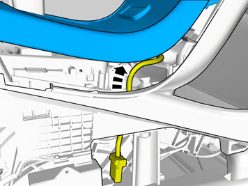
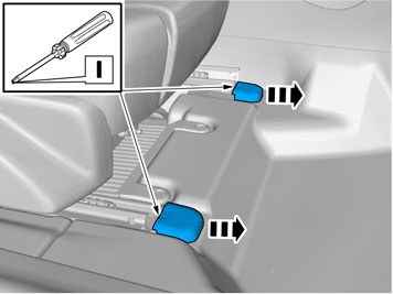
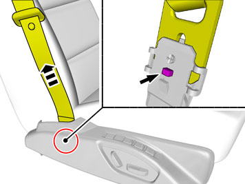
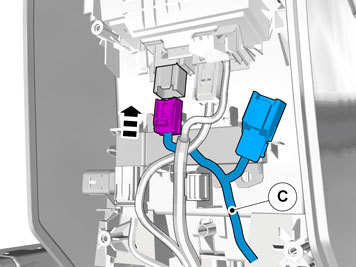
| | Loosen the screws. Disconnect the connector. |
|  | | IMG-329153 |
|
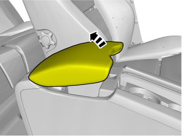
| | Caution!
Be extra careful when removing or installing this component. |
|
|  | | IMG-377070 |
|
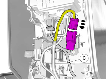
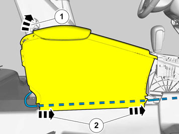
| | Repeat the steps when removing on opposite side. |
| | |
|  | | IMG-382637 |
|
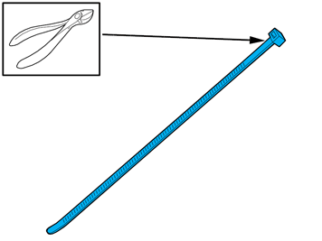
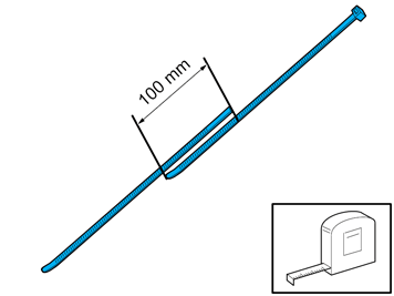
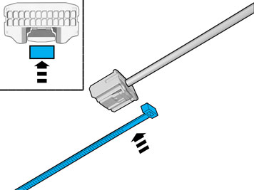
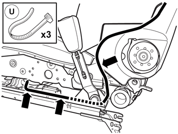
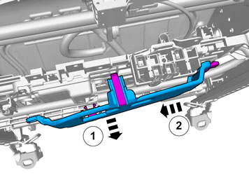
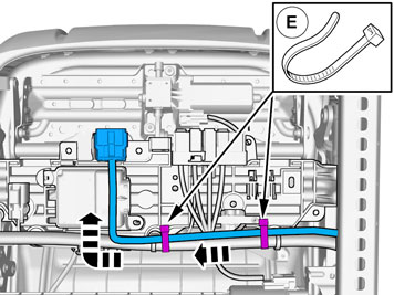
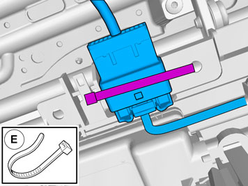
| | Use: 988734, Cable tie, 750 mm
|
|  | | IMG-382638 |
|
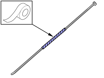
| | Use: 988734, Cable tie, 750 mm
|
|  | | IMG-372824 |
|
| | |
|  | | IMG-373154 |
|
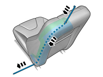
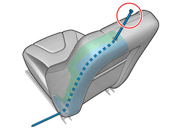
| | Thread the cable tie from the head restraint's inner mounting. Route the cable tie inside the backrest between the upholstery's thin foam and the impact protection. |
|  | | IMG-380827 |
|
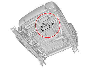
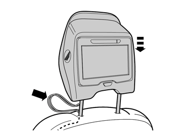
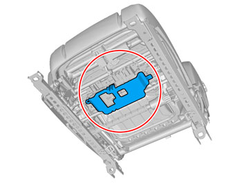
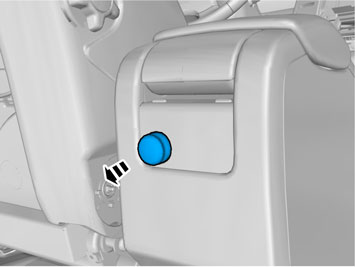
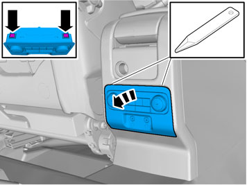
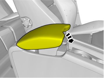
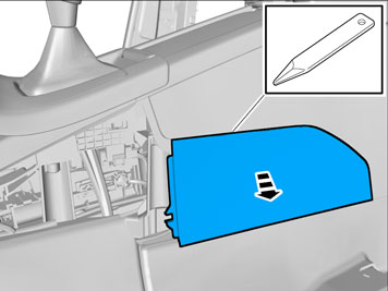
| | Place the component where indicated in the graphic. |
|  | | IMG-379508 |
|
| | |
|  | | IMG-379510 |
|
| | |
|  | | IMG-379514 |
|
| | |
|  | | IMG-379516 |
|
| | Pull the wiring through. Remove the tape. |
|  | | IMG-380828 |
|
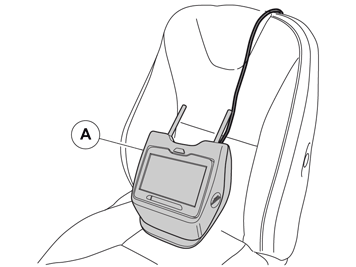
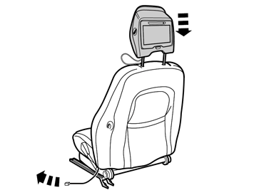
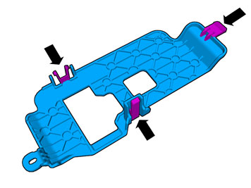
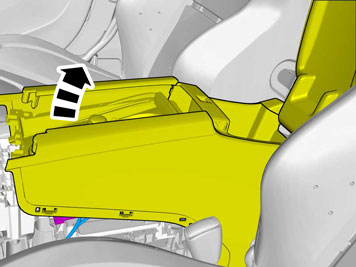
| | Place the component where indicated in the graphic. The cables must be positioned in front of the head restraint's tube. |
|  | | IMG-380829 |
|
| | |
|  | | IMG-380830 |
|
| | Caution!
Check that the component has locked in its bottom position. |
|
|  | | IMG-262956 |
|
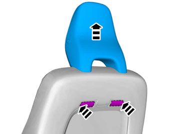
| | The image shows seat without upholstery. Using your fingers, push the cable harness under the protective pad. After installation, the cable harness must not appear under the upholstery. padding Protective pad
|
|  | | IMG-373320 |
|
| | Caution!
Make sure that no part of the wiring harness is trapped. |
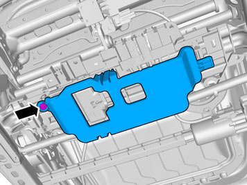
The image shows seat without upholstery. Route the cable harness to the existing cable harness. Install the cable. |
|  | | IMG-373201 |
|
| | |
|  | | IMG-373200 |
|
| | Note!
The graphic shows the back of the component before removal. |
|
|  | | IMG-373202 |
|
| | |
|  | | IMG-373206 |
|
| | |
|  | | IMG-380695 |
|
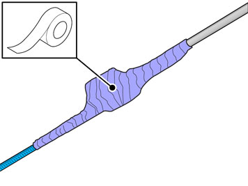
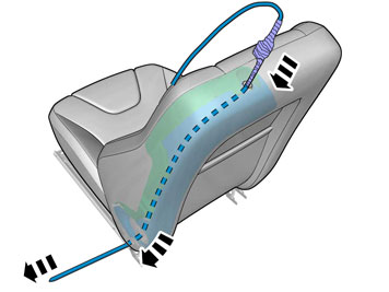
| | Note!
Extra cable length must be secured using cable ties. |
Install the cable. |
| | | IMG-377070 |
|
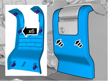
| | Repeat the steps when installing accessories on opposite side. |
| | |
|  | | IMG-293024 |
|
| | |
| | Vehicles with headset sockets |
|  | | IMG-293025 |
|
| | |
|  | | IMG-293026 |
|
| | Disconnect the connector. |
| | |
| | | IMG-293021 |
|
| | |
|  | | IMG-329163 |
|
| | |
|  | | IMG-293028 |
|
| | |
|  | | IMG-293029 |
|
| | |
|  | | IMG-329164 |
|
| | |
|  | | IMG-344819 |
|
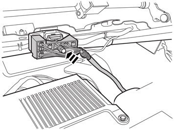
| | Disconnect the connector. |
|  | | IMG-344825 |
|
| | Install component that comes with the accessory kit. Connect the connector. |
|  | | IMG-344827 |
|
| | |
|  | | IMG-344828 |
|
| | Install the part with butyl tape. |
|  | | IMG-329435 |
|
| | |
| | | IMG-329164 |
|
| | Caution!
Make sure that no part of the wiring harness is trapped. |
Reinstall the removed part. |
|  | | IMG-345746 |
|
| | |
|  | | IMG-374497 |
|
| | |
|  | | IMG-374495 |
|
| | Locate the connector. Disconnect the connector. |
|  | | IMG-379240 |
|
| | Install component that comes with the accessory kit. Connect the connector. |
|  | | IMG-362040 |
|
| | |
|  | | IMG-382650 |
|
| | |
|  | | IMG-379247 |
|
| | Install component that comes with the accessory kit. |
|  | | IMG-379250 |
|
| | |
|  | | IMG-379345 |
|
| | |
|  | | IMG-379274 |
|
| | |
|  | | IMG-379278 |
|
| | |
|  | | IMG-382286 |
|
| | |
|  | | IMG-379293 |
|
| | |
|  | | IMG-379365 |
|
| | |
|  | | IMG-379367 |
|
| | |
|  | | IMG-379368 |
|
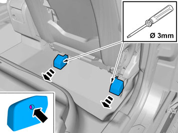
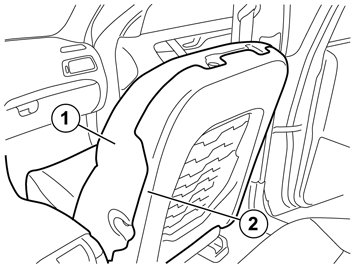
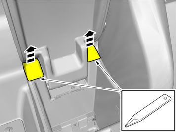
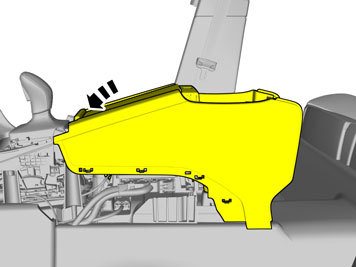
| | Fold the floor carpet back. |
|  | | IMG-379369 |
|
| | |
|  | | IMG-379485 |
|
| | |
| | |
|  | | IMG-329473 |
|
| | Caution!
Be extra careful when removing or installing this component. |
Reinstall the front seat. |
|  | | IMG-382653 |
|
| | |
|  | | IMG-372884 |
|
| | |
|  | | IMG-380703 |
|
| | Connect the cable harness. |
|  | | IMG-380704 |
|
| | |
|  | | IMG-329270 |
|
| | Connect the connector. Tighten the screw. |
|  | | IMG-382654 |
|
| | |
| | Repeat the steps when installing on opposite side. |
| | Reinstall the removed parts in reverse order. |
|  | | IMG-382312 |
|
| | |
|  | | IMG-382311 |
|
| | |
| | Place the manual for this accessory in a suitable location in the car. |
|  | | IMG-336901 |
|
| | Reinstall the battery's negative cable. |
|  | | IMG-336904 |
|
| | Warning!
When switching the ignition on for the first time after a battery disconnect and connect, make sure to stand outside the vehicle and only reach into the vehicle keeping clear of the air bag deployment areas. |
Set the ignition key to position II. |
|  | | IMG-382943 |
|
| | |
|  | | IMG-275777 |
|
| | Adapt the DVD player to the vehicle according to: Product specifications/Design and Function/3 Electrical system/39 Media - communication and entertainment/393 Equipment for entertainment/System for rear seat entertainment/Design |