| | |
| | Read through all of the instructions before starting installation. Notifications and warning texts are for your safety and to minimise the risk of something breaking during installation. Ensure that all tools stated in the instructions are available before starting installation. Certain steps in the instructions are only presented in the form of images. Explanatory text is also given for more complicated steps. In the event of any problems with the instructions or the accessory, contact your local Volvo dealer.
|
| | |
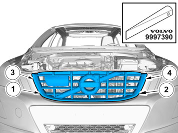
|  | | IMG-332179 |
|
| | Set the ignition key to position 0. Remove the battery's negative cable. |
| | |
|  | | IMG-363036 |
|
| | Note!
This colour chart displays (in colour print and electronic version) the importance of the different colours used in the images of the method steps. |
Used for focused component, the component with which you will do something. Used as extra colors when you need to show or differentiate additional parts. Used for attachments that are to be removed/installed. May be screws, clips, connectors, etc. Used when the component is not fully removed from the vehicle but only hung to the side. Used for standard tools and special tools. Used as background color for vehicle components.
|
| | |
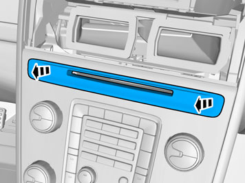
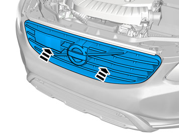
|  | | IMG-345728 |
|
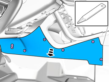
| | |
|  | | IMG-345734 |
|
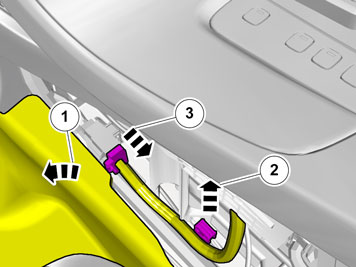
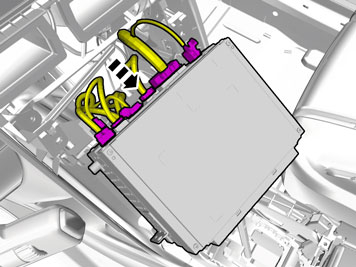
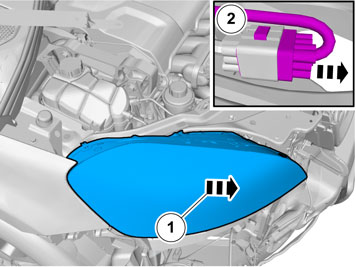
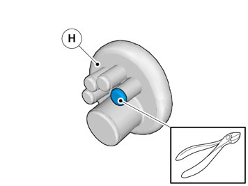
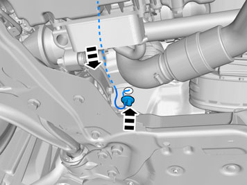
| | Disconnect the connector. |
|  | | IMG-345736 |
|
| | |
|  | | IMG-345737 |
|
| | |
|  | | IMG-345744 |
|
| | |
|  | | IMG-345745 |
|
| | |
|  | | IMG-340598 |
|
| | |
|  | | IMG-345746 |
|
| | |
|  | | IMG-340599 |
|
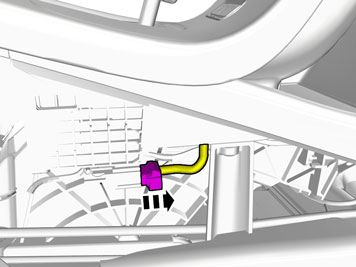
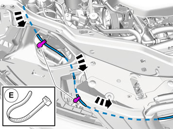
| | Fold the carpet to the side. Remove the cable harness clips. Disconnect the connector.
|
|  | | IMG-340600 |
|
| | |
| | Vehicles with the 4C system. |
|  | | IMG-340601 |
|
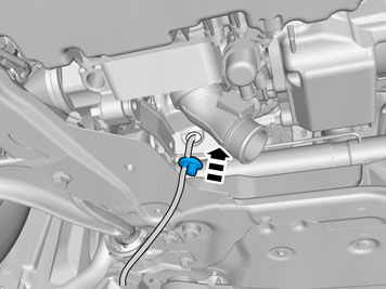
| | Disconnect the connector. |
| | |
|  | | IMG-340602 |
|
| | |
|  | | IMG-375923 |
|
| | |
|  | | IMG-293010 |
|
| | |
|  | | IMG-375925 |
|
| | |
|  | | IMG-345767 |
|
| | |
|  | | IMG-345766 |
|
| | |
|  | | IMG-345769 |
|
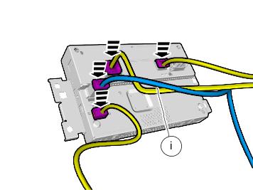
| | Disconnect the connectors. |
|  | | IMG-341780 |
|
| | |
|  | | IMG-341781 |
|
| | |
|  | | IMG-341782 |
|
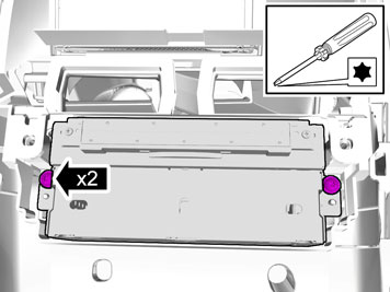
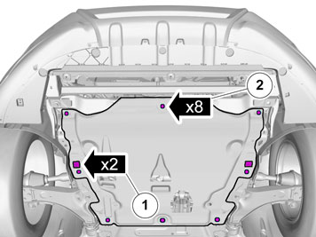
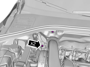
| | Remove the screws.
Tightening torque: M8
, 24 Nm
|
|  | | IMG-341773 |
|
| | |
|  | | IMG-374438 |
|
| | |
|  | | IMG-374497 |
|
| | |
|  | | IMG-346026 |
|
| |
Tightening torque: M8
, 24 Nm
|
|  | | IMG-341771 |
|
| |
Tightening torque: M8
, 24 Nm
|
|  | | IMG-341746 |
|
| |
Tightening torque: M8
, 24 Nm
|
|  | | IMG-345770 |
|
| | |
|  | | IMG-346281 |
|
| | |
|  | | IMG-345774 |
|
| | |
|  | | IMG-345773 |
|
| | |
|  | | IMG-345776 |
|
| | Disconnect the connectors. |
|  | | IMG-374495 |
|
| | Disconnect the connector. |
|  | | IMG-374547 |
|
| | Install component that comes with the accessory kit. |
|  | | IMG-362040 |
|
| | Locate the existing connector in the vehicle's cable harness. Connect the connector. |
|  | | IMG-374510 |
|
| | Tear off the excess foam tape. Clamp the cables and connectors to the existing cables to prevent noise. |
|  | | IMG-345849 |
|
| | |
|  | | IMG-345850 |
|
| | |
|  | | IMG-345851 |
|
| | |
|  | | IMG-345856 |
|
| | |
|  | | IMG-345857 |
|
| | |
|  | | IMG-345858 |
|
| | |
|  | | IMG-345859 |
|
| | |
|  | | IMG-307603 |
|
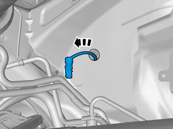
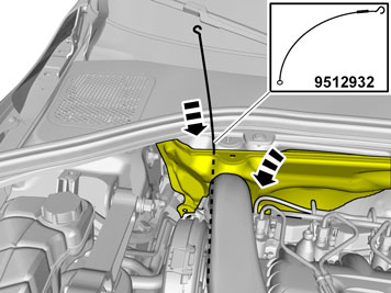
| | Locate the rubber grommet under the insulation and press it out. |
|  | | IMG-345860 |
|
| | |
|  | | IMG-345861 |
|
| | |
|  | | IMG-345862 |
|
| | |
| | | IMG-345767 |
|
| | |
|  | | IMG-345863 |
|
| | |
|  | | IMG-345864 |
|
| | |
| | | IMG-345774 |
|
| | |
| | Reinstall the removed parts in reverse order. |
| | |
|  | | IMG-375942 |
|
| | |
|  | | IMG-374212 |
|
| | Measure and mark as illustrated. Use: Scribe
|
|  | | IMG-374213 |
|
| | |
|  | | IMG-374224 |
|
| |
Use special tool: T9995919, PULLER (SEAL-PINION,CAM-CRANKSHAFT)B200-6304
|
|  | | IMG-374215 |
|
| | |
|  | | IMG-374217 |
|
| | |
| | |
|  | | IMG-345865 |
|
| | |
|  | | IMG-345866 |
|
| | |
|  | | IMG-345867 |
|
| | |
|  | | IMG-345871 |
|
| | |
|  | | IMG-345872 |
|
| | |
|  | | IMG-345873 |
|
| | Remove the part carefully |
|  | | IMG-345874 |
|
| | |
|  | | IMG-345875 |
|
| | |
|  | | IMG-345876 |
|
| | |
|  | | IMG-307687 |
|
| | |
|  | | IMG-307688 |
|
| | |
|  | | IMG-345877 |
|
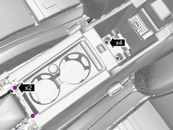
| | Remove the clips. Remove the screws.
|
|  | | IMG-345878 |
|
| | |
|  | | IMG-345879 |
|
| | Locate the rubber grommet under the insulating mat. |
|  | | IMG-345880 |
|
| | |
|  | | IMG-345881 |
|
| | |
|  | | IMG-345882 |
|
| | Use: Expander pliers
Use: 1161427, Low temperature grease
|
|  | | IMG-345883 |
|
| | |
|  | | IMG-273585 |
|
| | |
|  | | IMG-340533 |
|
| | |
|  | | IMG-340606 |
|
| | |
|  | | IMG-345884 |
|
| | |
|  | | IMG-345885 |
|
| | Caution!
Make sure to locate the wiring in such a way that any damage caused by heat or excessive wear is avoided. |
Note!
Do not yet tighten the clamps. |
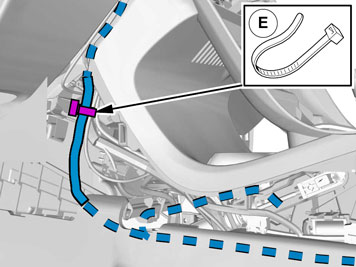
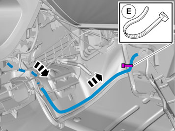
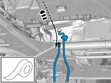
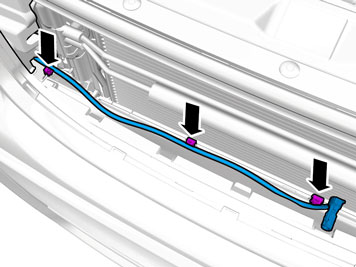
Route the ground wire next to the existing wiring harness. |
|  | | IMG-345886 |
|
| | |
|  | | IMG-345887 |
|
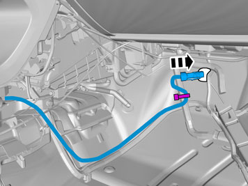
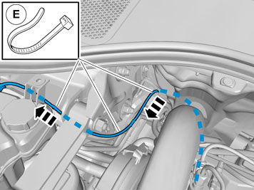
| | Route the cable harness to the existing cable harness. |
|  | | IMG-345888 |
|
| | |
|  | | IMG-345889 |
|
| | |
|  | | IMG-345890 |
|
| | Caution!
Tighten clamps properly. |
|
|  | | IMG-347781 |
|
| | |
|  | | IMG-347786 |
|
| | |
|  | | IMG-375872 |
|
| | Note!
This step is easier with two people. |
|
|  | | IMG-375871 |
|
| | Use: Angle drill machine
Use special tool: T9997482, Cutting tool
|
|  | | IMG-375843 |
|
| | Use: Angle drill machine
Use special tool: T9997482, Cutting tool
|
|  | | IMG-375883 |
|
| | |
| | | IMG-347781 |
|
| | |
| | | IMG-347786 |
|
| | |
|  | | IMG-374396 |
|
| | |
|  | | IMG-374391 |
|
| | |
|  | | IMG-375891 |
|
| | |
|  | | IMG-375895 |
|
| | |
|  | | IMG-340544 |
|
| | Caution!
Tighten clamps properly. |
Insert the cable in to the passenger compartment, adjust the cable length out into the engine compartment and secure the rubber grommet. Reinstall the removed parts in reverse order. |
|  | | IMG-242268 |
|
| | Download software (application) for the accessory's function according to the service information in VIDA. Order and download software according to: 31285245
|