| | |
|  | | IMG-247309 |
|
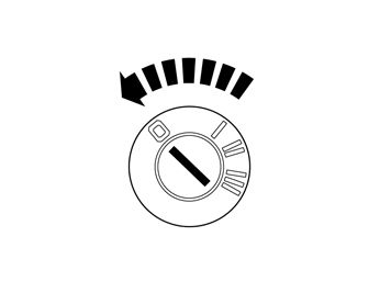
| | Turn the ignition switch to position 0. Note!
Wait at least one minute before unplugging the connectors or removing other electrical equipment. |
|
|  | | IMG-232587 |
|
| | |
|  | | IMG-232588 |
|
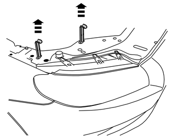
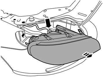
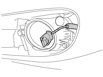
| | Unplug the connector Remove the headlamp.
|
|  | | IMG-239480 |
|
| | |
|  | | IMG-239481 |
|
| | |
|  | | IMG-231309 |
|
| | |
|  | | IMG-236054 |
|
| | |
|  | | IMG-217703 |
|
| | Note!
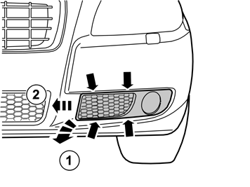
Do not damage the paint work. |
|
|  | | IMG-249043 |
|
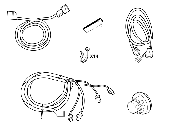
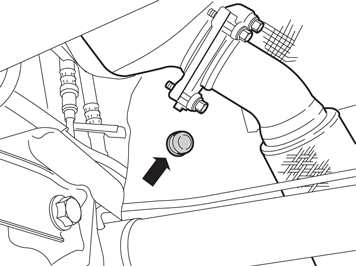
| | Take the cable harness for sensors from the kit Route the connector from the inside and out through the hole, on the outside of the fog lamp Repeat the operation on the other side
Note!
On left-hand drive cars the large gray connector must be on the right-hand side. On right-hand drive cars it must be on the left-hand side. |
|
| 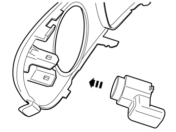 | | IMG-249044 |
|
| | |
| 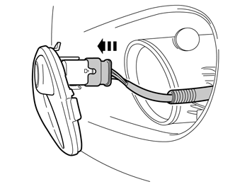 | | IMG-249045 |
|
| | |
|  | | IMG-217713 |
|
| | |
| 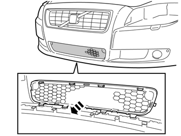 | | IMG-249163 |
|
| | |
|  | | IMG-249164 |
|
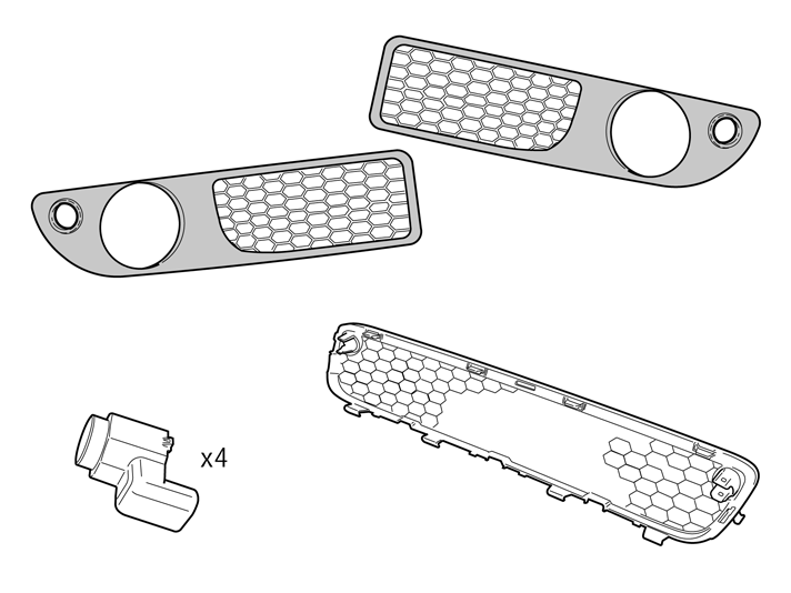
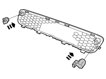
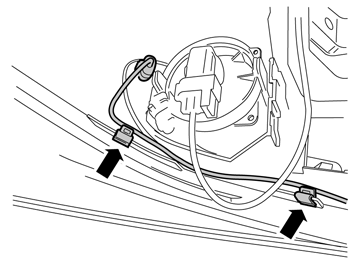
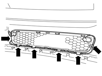
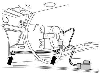
| | Take the new central grille and install the two sensors. Press the grille into the bumper. Check that all hooks engage. Connect the remaining connectors to the sensors.
|
|  | | IMG-249165 |
|
| | |
|  | | IMG-249166 |
|
| | |
|  | | IMG-249167 |
|
| | |
|  | | IMG-249168 |
|
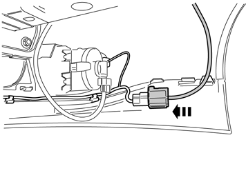
| | Take the short cable harness from the kit. Remove the taped connector from the cable. Install the large connector to the cable harness from the sensors.
|
|  | | IMG-249169 |
|
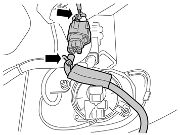
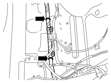
| | Route the cable harness on the outside of the side member, up to the headlamp. Secure the connector using two tie straps at the existing cable harness. Lower the car.
|
|  | | IMG-249170 |
|
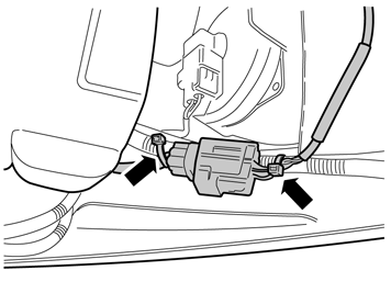
| | Applies to right-hand drive cars Route the cable harness on the outside of the side member, up to the headlamp. Secure the connector using two tie straps at the cable holder (the clip) on the cable harness from the sensors. Lower the car.
|
|  | | IMG-239420 |
|
| | |
|  | | IMG-249172 |
|
| | |
|  | | IMG-222267 |
|
| | |
|  | | IMG-231433 |
|
| | |
|  | | IMG-222268 |
|
| | |
|  | | IMG-225205 |
|
| | |
|  | | IMG-225201 |
|
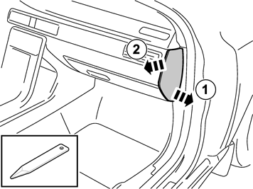
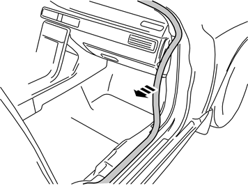
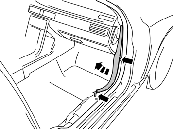
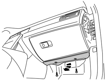
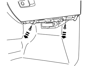
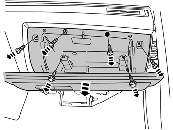
| | Remove the seven screws. Cut off the glovebox lighting tie strap, on the reverse of the glovebox. Pull the glovebox out slightly and disconnect the gray connector on the rear side. Remove the glovebox.
|
|  | | IMG-239483 |
|
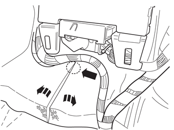
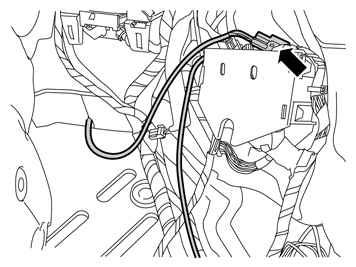
| | Move the carpeting aside. Make a cut in the thick insulating mat starting level with the blue connector of the central electronic module (CEM) and then continue straight down. Move aside the insulating mat to access the grommet.
|
|  | | IMG-235947 |
|
| | Note!
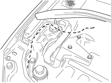
Make sure that the cable is positioned so that it is not damaged by heat or wear. |
Reinstall the headlamp. Raise the car.
|
|  | | IMG-235950 |
|
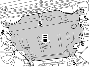
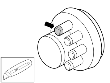
| | Cut off a small rubber nipple on the new rubber grommet and thread the cable through. Pull the cable into the passenger compartment. Adjust the length. Install the rubber grommet and move the heat shield on the cable against the rubber grommet. Reinstall the engine splash guard and cover panel for the bumper. Lower the car.
|
|  | | IMG-249173 |
|
| | |
|  | | IMG-249174 |
|
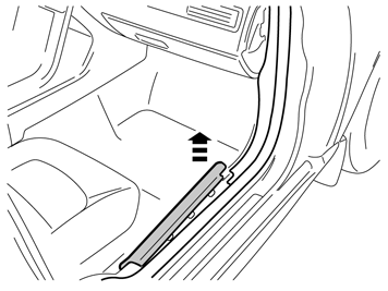
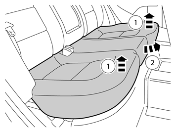
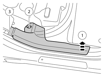
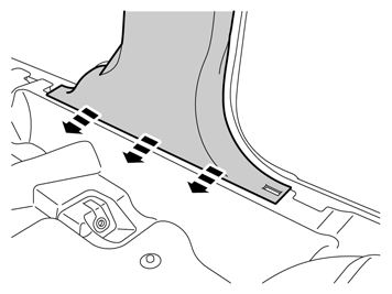
| | Remove the rear sill trim panel by pulling it up at the front edge (1) and then unhooking it from the clip (2). Push the side cushion at the lower edge to one side and pull the panel so that the last clip (3) releases.
|
|  | | IMG-249175 |
|
| | |
|  | | IMG-249176 |
|
| | |
|  | | IMG-249177 |
|
| | |
|  | | IMG-249178 |
|
| | |
|  | | IMG-226722 |
|
| | |
|  | | IMG-249179 |
|
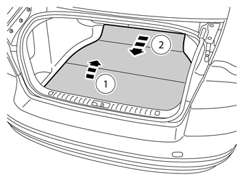
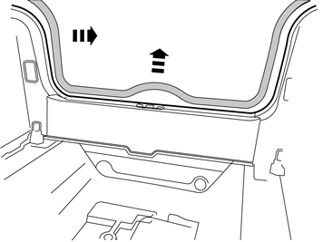
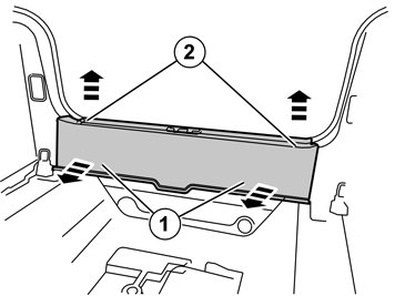
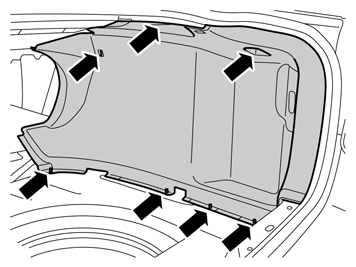
| | Remove the four plastic nuts at the lower edge. Lift off the panel from the studs. Remove the three clips. Lift off the panel and remove the connectors for cargo compartment lighting and any 12 Volt socket. On right-hand drive cars, both the side panels must be removed.
|
|  | | J3703487 |
|
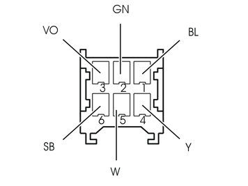
| | Applies to left-hand drive cars Take the connector that was taped and connect it to the cable harness that was routed into the passenger compartment. Install the pins for the cable ends into the connector as illustrated.
Blue (BL) Green (GN) Violet (VO) Yellow (Y) White (W) Black (SB)
|
|  | | IMG-249180 |
|
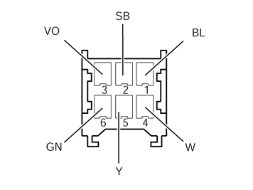
| | Applies to right-hand drive cars Take the connector that was taped and connect it to the cable harness that was routed into the passenger compartment. Install the pins for the cable ends into the connector as illustrated.
Blue (BL) Black (SB) Violet (VO) White (W) Yellow (Y) Green (GN)
|
|  | | IMG-249181 |
|
| | |
|  | | IMG-249182 |
|
| | |
|  | | IMG-249183 |
|
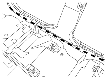
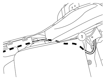
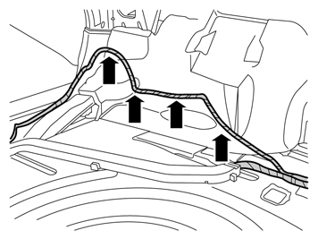
| | Route the cable harness under the side cushion, on the outside of the mounting for the seat belt and under the backrest's lower mounting. Then follow the car's cable harness backwards. Secure the it with a tie strap (1).
|
|  | | IMG-249184 |
|
| | |
|  | | IMG-249185 |
|
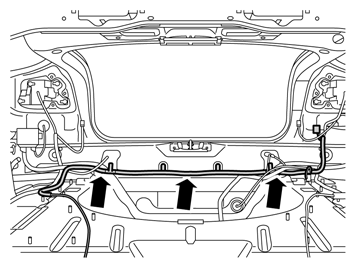
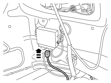
| | Applies to right-hand drive cars Route the cable harness along the existing cable harness at the rear member, to the right-hand side where the parking assistance module (PAM) is located. Secure with three tie straps.
|
|  | | IMG-249186 |
|
| | |
|  | | IMG-249187 |
|
| | |
| | Cargo compartment Reinstall: side panel sill trim panel sill molding the cargo compartment carpeting. |
| | Passenger compartment Fold the carpeting back at the passenger seat and B pillar. Reinstall: glovebox and new tie strap to the glovebox lighting. Tighten the two M6 screws to 10 Nm (7.3 lbf.ft). sound proofing the sill trim panels end panel sill molding rear seat. |
|  | | IMG-242268 |
|
| | Download the software for the accessory's function following the service information in VIDA. Check the function of the accessory. |

