| | |
| | Read through all of the instructions before starting installation. Notifications and warning texts are for your safety and to minimise the risk of something breaking during installation. Ensure that all tools stated in the instructions are available before starting installation. Certain steps in the instructions are only presented in the form of images. Explanatory text is also given for more complicated steps. In the event of any problems with the instructions or the accessory, contact your local Volvo dealer.
|
| | |
| | After installation, the car must not be washed for 48 hours |
| | |
|  | | IMG-363036 |
|
| | Note!
This colour chart displays (in colour print and electronic version) the importance of the different colours used in the images of the method steps. |
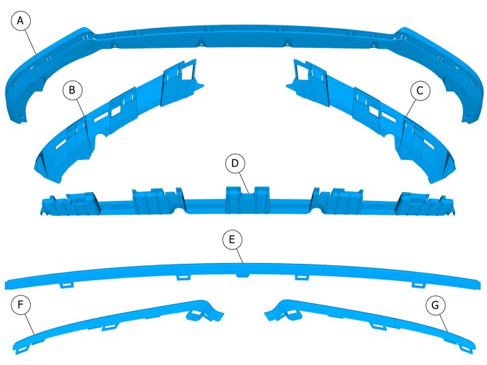
Used for focused component, the component with which you will do something. Used as extra colors when you need to show or differentiate additional parts. Used for attachments that are to be removed/installed. May be screws, clips, connectors, etc. Used when the component is not fully removed from the vehicle but only hung to the side. Used for standard tools and special tools. Used as background color for vehicle components.
|
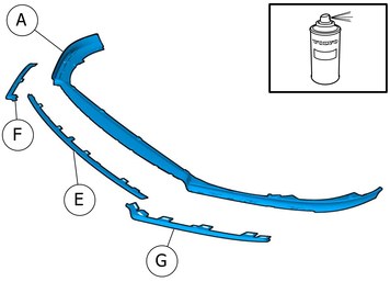
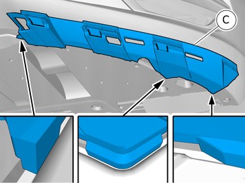
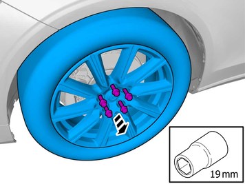
| | Applies to unpainted component |
|  | | IMG-416151 |
|
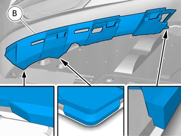
| | |
| | |
| | |
|  | | IMG-415823 |
|
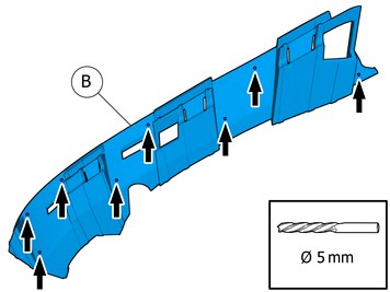
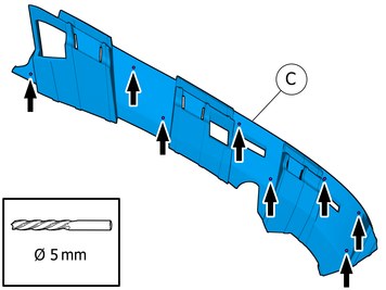
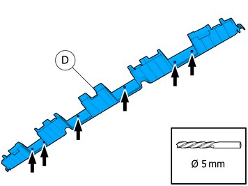
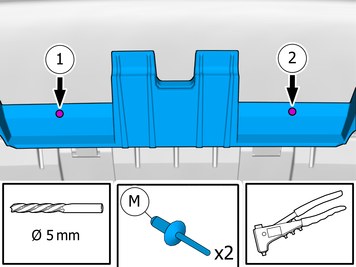
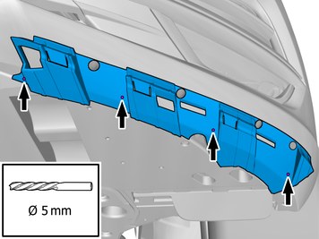
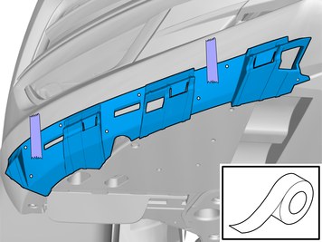
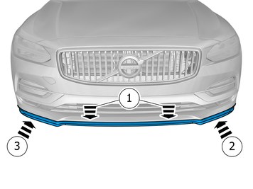
| | Locate relevant marking. Use a drill with the stated size |
|  | | IMG-415824 |
|
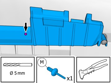
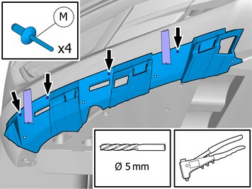
| | Locate relevant marking. Use a drill with the stated size |
|  | | IMG-415822 |
|
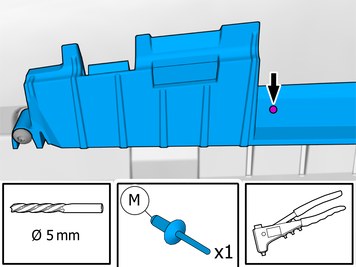
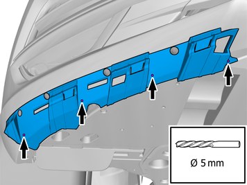
| | Locate relevant marking. Use a drill with the stated size |
| | |
| | Note!
The removal steps may contain installation details. |
|
|  | | IMG-415832 |
|
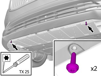
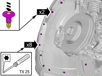
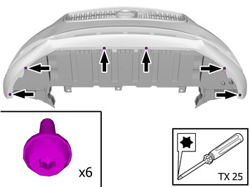
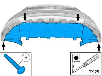
| | Remove the screws. The part is not to be reused. |
| | |
|  | | IMG-415833 |
|
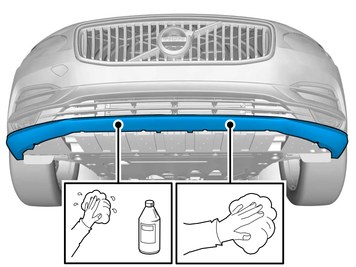
| | Clean the surface. Wipe dry. Use: 1161721, Isopropanol
|
|  | | IMG-415836 |
|
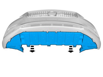
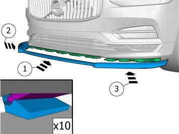
| | Install component that comes with the accessory kit. Use hands only. |
|  | | IMG-415845 |
|
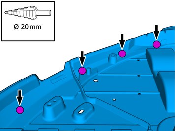
| | Drill one hole and fit one pop rivet at a time, in accordance with the sequence illustrated. |
|  | | IMG-415846 |
|
| | Drill one hole and fit one pop rivet at a time, in accordance with the sequence illustrated. |
|  | | IMG-415847 |
|
| | Drill one hole and fit one pop rivet at a time, in accordance with the sequence illustrated. |
|  | | IMG-415850 |
|
| | Remove the screw. Repeat on the other side. |
|  | | IMG-415877 |
|
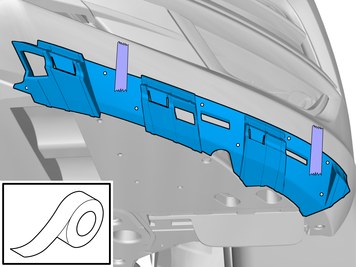
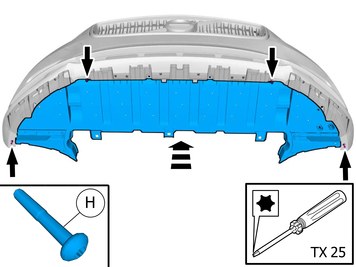
| | Install component that comes with the accessory kit. |
|  | | IMG-415878 |
|
| | |
|  | | IMG-415879 |
|
| | Drill one hole and fit one pop rivet at a time, in accordance with the sequence illustrated. Remove the tape. |
|  | | IMG-415880 |
|
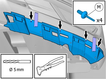
| | Use a drill with the stated size |
|  | | IMG-415966 |
|
| | Install component that comes with the accessory kit. |
|  | | IMG-415967 |
|
| | |
|  | | IMG-415968 |
|
| | Drill one hole and fit one pop rivet at a time, in accordance with the sequence illustrated. Remove the tape. |
|  | | IMG-415969 |
|
| | Use a drill with the stated size |
| | |
|  | | IMG-417690 |
|
| | |
|  | | IMG-412677 |
|
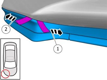
| | Remove the clips. Remove the marked part. Repeat on the other side. |
|  | | IMG-412680 |
|
| | Remove the clip. Remove the marked part. |
|  | | IMG-412681 |
|
| | |
|  | | IMG-403425 |
|
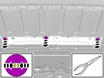
| | Remove the marked part. Use: Pliers
|
|  | | IMG-415975 |
|
| | |
|  | | IMG-412692 |
|
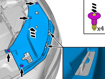
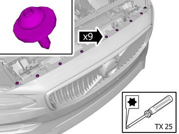
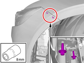
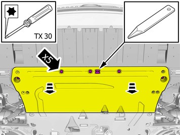
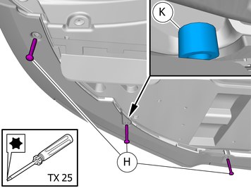
| | Remove the clips. Remove the screws. |
|  | | IMG-412697 |
|
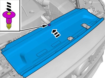
| | |
|  | | IMG-412710 |
|
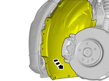
| | Fold the wing liner aside. |
|  | | IMG-412715 |
|
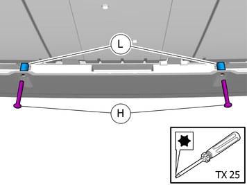
| | Remove the screws.
Tightening torque: Bracket to front fender
, 6 Nm
|
| | Repeat the steps when removing on opposite side. |
| | Vehicles with headlamp washers |
|  | | IMG-412745 |
|
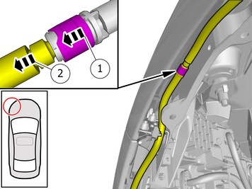
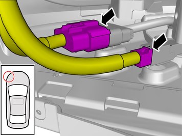
| | Release the lock. Undo the hose from the connection.
|
|  | | IMG-412750 |
|
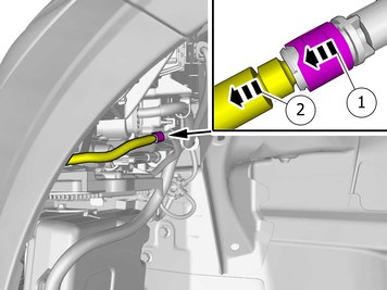
| | Release the lock. Undo the hose from the connection.
Repeat on the other side. |
| | |
|  | | IMG-412730 |
|
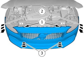
| | Caution!
The number of connectors can vary depending on the vehicle's equipment level. |
Disconnect the connectors. |
|  | | IMG-412779 |
|
| | Remove the screws. Remove the clip. Fold marked part aside. |
|  | | IMG-412725 |
|
| | |
|  | | IMG-412771 |
|
| | Caution!
Place the component on a suitable underlay or support. |
Note!
This step requires the aid of another technician. |
Release the catches. Remove the part carefully Remove the marked part.
|
|  | | IMG-415982 |
|
| | Remove the screws. The part is not to be reused. |
|  | | IMG-412673 |
|
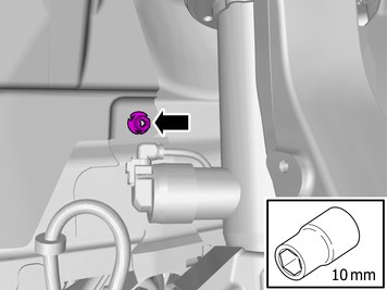
| | Loosen the component indicated. Do not remove it. |
|  | | IMG-415999 |
|
| | Use a drill with the stated size Drill the holes. Repeat on the other side. |
| | |
|  | | IMG-416003 |
|
| | Reinstall the removed part. Install the screws. |
|  | | IMG-423240 |
|
| | Note!
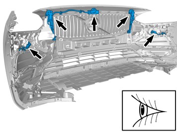
Make sure that the pedestrian protection sensors are correctly and properly secured in their brackets and that the wiring and connectors show no signs of damage. |
|
|  | | IMG-419443 |
|
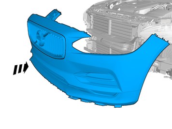
| | Note!
This step requires the aid of another technician. |
Reinstall the bumper. |
| | Reinstall the removed parts in reverse order. |
| | |
|  | | IMG-416004 |
|
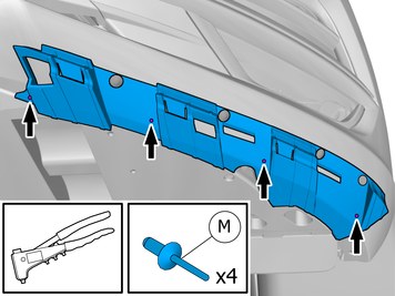
| | Install component that comes with the accessory kit. Repeat on the other side. |
|  | | IMG-416041 |
|
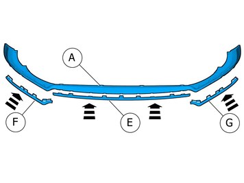
| | Install component that comes with the accessory kit. Ensure that all clips engage. |
| | |
|  | | IMG-416085 |
|
| | |
| | |
|  | | IMG-430012 |
|
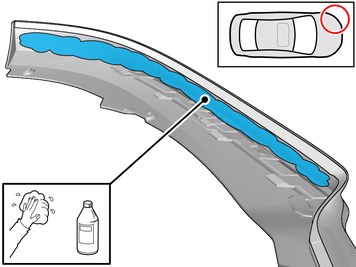
| | Clean the surface. Use: 1161721, Cleaning agent
Wipe dry. |
|  | | IMG-430020 |
|
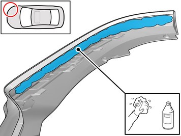
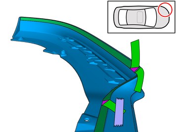
| | Clean the surface. Use: 1161721, Cleaning agent
Wipe dry. |
|  | | IMG-411869 |
|
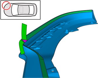
| | Caution!
Cut carefully to avoid unintentional damage or personal injury. |
Cut the component following the instructions in the graphic. |
|  | | IMG-430021 |
|
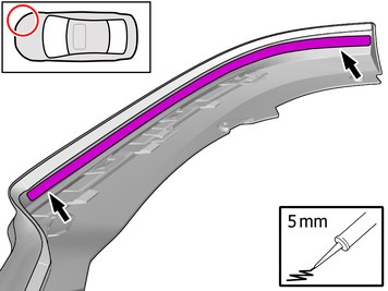
| | Apply the stated Material on the marked surface. Use: 1161767, Sealing compound
|
|  | | IMG-430022 |
|
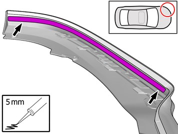
| | Apply the stated Material on the marked surface. Use: 1161767, Sealing compound
|
|  | | IMG-416130 |
|
| | Fold the protective film forward |
|  | | IMG-416153 |
|
| | Fold the protective film forward |
|  | | IMG-416110 |
|
| | Install component that comes with the accessory kit. Ensure that all clips engage. |
|  | | IMG-416135 |
|
| | Install component that comes with the accessory kit. |
|  | | IMG-430073 |
|
| | Install component that comes with the accessory kit. Repeat on the other side. |
|  | | IMG-416138 |
|
| | Remove the protective film. |
|  | | IMG-416137 |
|
| | Remove the protective film. |
|  | | IMG-419861 |
|
| | Note!
Press and apply pressure to the part over the tape for at least 20 seconds. |
Note!
Ensure that the tape is fixed to the surface. |
|
| | |
|  | | IMG-405228 |
|
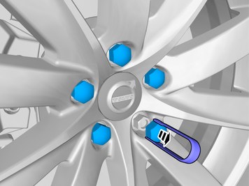
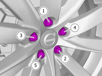
| | Note!
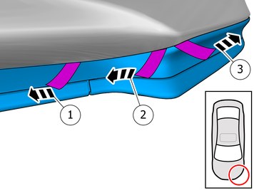
Make sure to follow the sequence indicated. |
Tightening torque: Aluminum wheel rim to wheel hub
Stage 1:
4 Nm
Stage 2:
50 Nm
Stage 3:
140 Nm
|