| | Applies to the S40 (04–) and V50 |
|  | | IMG-332193 |
|
| | Applies to the S40 (04–) and V50 |
|  | | IMG-346192 |
|
| | |
|  | | J8601058 |
|
| | |
|  | | J8504526 |
|
| | |
|  | | J8504527 |
|
| | |
| | |
|  | | IMG-273472 |
|
| | |
|  | | IMG-273474 |
|
| | Prize off the four external clips at the front edge/bottom edge of the sill trim panel on the tailgate. Pry up one of the corners of the sill trim panel so that the two clips at that end release. Use a weatherstrip tool. Pull up the sill trim panel so the remaining six clips release. Remove the panel.
|
|  | | J8504578 |
|
| | |
|  | | J8504708 |
|
| | |
|  | | IMG-240927 |
|
| | |
|  | | J8504585 |
|
| | Pull off the rubber strip at the rear of the opening for the right-hand rear door. Carefully pry off the lower panel on the C-post on the right-hand side. Pry the top edge using a weatherstrip tool. Pull in the C-post panel so that the two upper clips release. Then continue pulling down until the last two clips release.
|
|  | | IMG-347037 |
|
| | Fold out the anchorage eyelets. Insert a scriber with an angled tip into the holes in the top of the covers (1). Turn the scriber so that the tip engages the reverse of the covers. Pull the covers off. Remove the screws from the anchorage eyelets (2). Remove the screw (3). Pull off the side panel at the top so that the two clips at the rear/bottom of the side window and the clip at the bottom of the D-pillar release. Disconnect the connector for the 12V socket, if present. Lift out the side panel.
|
|  | | J3904767 |
|
| | Applies to cars with reversing warning systems Remove the back-up (reversing) warning system (PAS) from behind the right-hand wheel arch, to facilitate access to route the cable harness to the tow bar. If necessary, disconnect any surrounding wiring.
|
|  | | J8504615 |
|
| | |
| | |
|  | | J8504553 |
|
| | |
|  | | J8504552 |
|
| | |
|  | | J8504554 |
|
| | Unscrew the two external clips at the front edge/bottom edge of the sill trim panel on the tailgate. Pry up one of the corners of the sill trim panel using a weatherstrip tool so that the two clips at that end release. Pull up the sill trim panel at the other end so that the remaining two clips release. Remove the sill trim panel.
|
|  | | J8504691 |
|
| | Remove the three clips (1) that hold the right-hand side panel in the bodywork. Unhook the side panel from the mounting (2) on the underneath of the parcel shelf. Fold out the rear edge of the side panel from the bodywork. At the same time unhook the side panel from the rear load securing eyelet. If the car has a 12V socket in the side panel, disconnect the connector from this socket (if applicable). Fold out the side panel to access the space in the rear of the wheel arch.
|
|  | | J3904768 |
|
| | Applies to cars with reversing warning systems Remove the back-up (reversing) warning system (PAS) from behind the right-hand wheel arch, to facilitate access to route the cable harness to the tow bar. If necessary, disconnect any surrounding wiring.
|
| | Installing the trailer hitch connector, applies to the S40 (04-) and V50 |
|  | | J8903198 |
|
| | Installing the trailer hitch connector, applies to the S40 (04-) and V50 |
|  | | IMG-273184 |
|
| | |
|  | | IMG-273185 |
|
| | |
|  | | IMG-273333 |
|
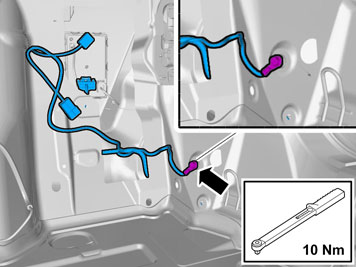
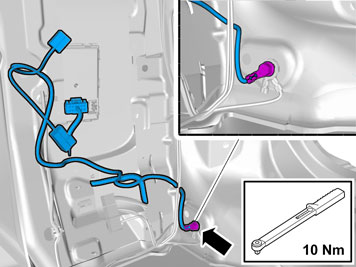
| | Applies to all models Route the cable down underneath the collision member's right-hand mounting and secure it using the joined cable ties from the kit. Secure the cable at the collision member with two joined cable ties from the kit.
|
|  | | J8903624 |
|
| | |
|  | | IMG-272768 |
|
| | |
|  | | J8903538 |
|
| | Applies to V50 models without RTI |
|  | | J8903539 |
|
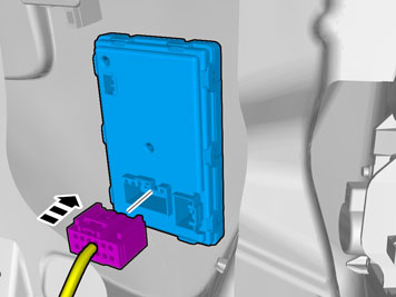
| | Applies to V50 models with RTI Remove the screws and the nuts holding the AM/FM tuner module (AFM) and the traffic message channel module (TMC) in the bodywork. Remove the AM/FM tuner module (AFM) and the traffic message channel module (TMC) from the bodywork. Disconnect the wiring if necessary. Place the AM/FM tuner module (AFM) and the traffic message channel module (TMC) to one side.
|
|  | | J8903623 |
|
| | |
|  | | IMG-347737 |
|
| | Use: Electrician's screwdriver |
|  | | IMG-359666 |
|
| | Position | Cable | Function | 1 | Pink | Reversing lamp | 2 | | Not used | 3 | White | Ground | 4 | | Not used | 5 | Grey | Power supply | 6 | | Not used | 7 | Brown | Right parking lamps | 8 | Black | Left parking lamps | 9 | Green | Right indicator lamps | 10 | Yellow | Left indicator lamps | 11 | Red | Brake lamp | 12 | Blue | Fog lights |
|
|  | | IMG-227863 |
|
| | |
|  | | IMG-359686 |
|
| | |
|  | | IMG-359806 |
|
| | |
|  | | IMG-359695 |
|
| | |
|  | | IMG-359813 |
|
| | |
|  | | IMG-359822 |
|
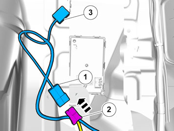
| | Connect the white 2 pin male connector (1) in the pre-routed cable harness, to the existing white clamped 2 pin female connector (2) at the rear edge of the wheel housing. Take a cable tie from the kit and clamp the remaining white connector (3) on the pre-routed cable harness at existing cables at the rear edge of the wheel housing.
|
|  | | IMG-359823 |
|
| | Applies to cars with a 12V socket Connect the white 2 pin female connector (1) that was disconnected from the 12 V socket to the white 2 pin male connector (2) on the routed cable harness. Connect the remaining white 2 pin female connector (3) on the routed cable harness to the 12 V socket.
|
|  | | IMG-348017 |
|
| | Applies to all models Note!
For correct function, the trailer module (TRM) must be programmed with software before checks can be carried out. |
Note!
To activate the trailer module (TRM) at least two light sources (lamps) must be connected. This can be done by connecting test equipment for the trailer connector or a trailer. |
Position | Function | 1 | Left indicator lamps | 2 | Rear fog lamp | 3 | Ground | 4 | Right indicator lamps | 5 | Right rear position lamp | 6 | Brake lamp | 7 | Left rear running light | 8 | Tail lamp | 9 | Power supply | 10 | Charging | 11 | Charging Ground | 12 | Trailer indicator | 13 | Ground |
|
| | |