| | |
| | Read through all of the instructions before starting installation. Notifications and warning texts are for your safety and to minimise the risk of something breaking during installation. Ensure that all tools stated in the instructions are available before starting installation. Certain steps in the instructions are only presented in the form of images. Explanatory text is also given for more complicated steps. In the event of any problems with the instructions or the accessory, contact your local Volvo dealer.
|
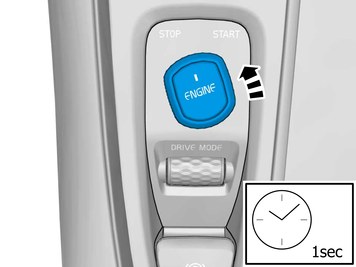
| | Disconnecting the battery |
|  | | IMG-394535 |
|
| | |
|  | | IMG-400002 |
|
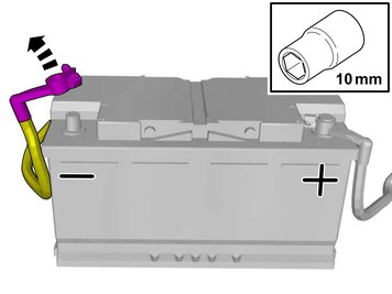
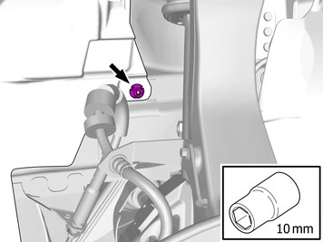
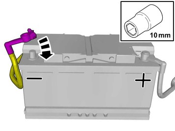
| | Remove the battery's negative cable. |
| | |
|  | | IMG-466880 |
|
| | |
|  | | IMG-412677 |
|
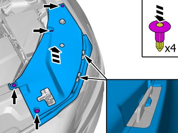
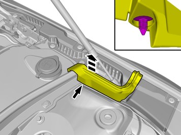
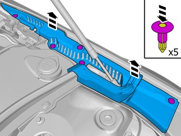
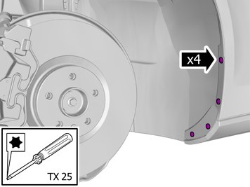
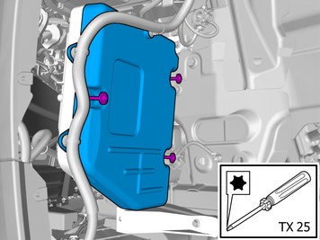
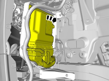
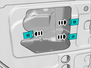
| | Remove the clips. Remove the marked part. |
|  | | IMG-449526 |
|
| | |
|  | | IMG-449531 |
|
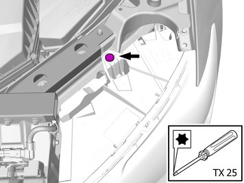
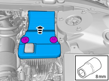
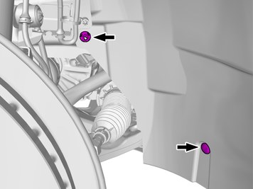
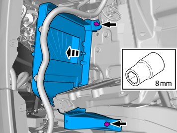
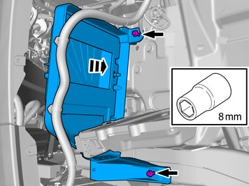
| | Remove the screws. Remove the marked part. |
| | Vehicles with diesel engines |
|  | | IMG-449491 |
|
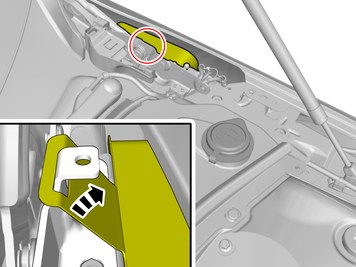
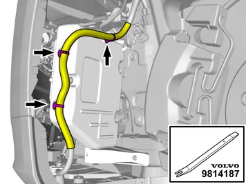
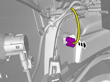
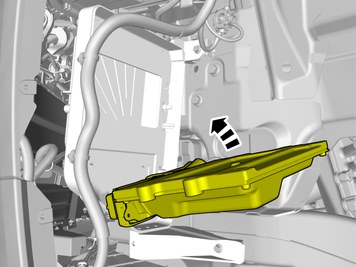
| | Loosen the marked detail. |
|  | | IMG-449492 |
|
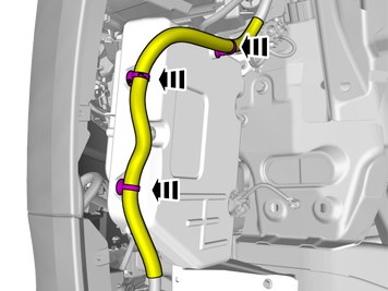
| | Remove the clips. Remove the marked part. |
|  | | IMG-449500 |
|
| | |
| | |
|  | | IMG-466882 |
|
| | |
|  | | IMG-403425 |
|
| | Remove the marked detail/details. Use: Pliers 31423632
|
|  | | IMG-415975 |
|
| | Remove the screws. Remove the marked part. |
|  | | IMG-466883 |
|
| | Remove the clips. Remove the screws. |
|  | | IMG-448299 |
|
| | |
|  | | IMG-421164 |
|
| | |
|  | | IMG-421165 |
|
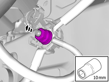
| | Remove the nut. Remove the clip. |
|  | | IMG-421166 |
|
| | |
|  | | IMG-448503 |
|
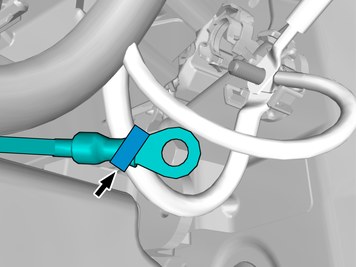
| | Remove the cable harness clips. |
|  | | IMG-448504 |
|
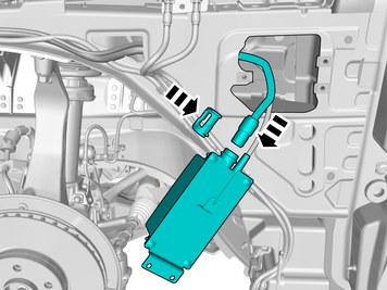
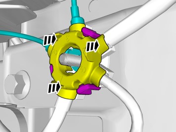
| | Loosen the screws. Remove the marked part. |
|  | | IMG-448505 |
|
| | Caution!
Take extra care when handling the component. |
Fold marked part aside. |
|  | | IMG-448506 |
|
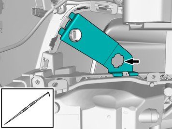
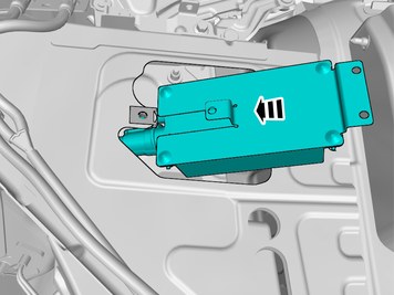
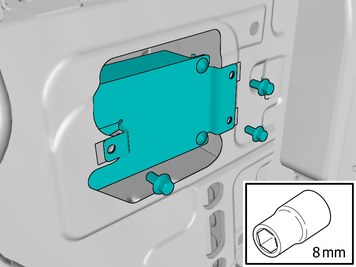
| | Remove the screws. Remove the marked part. |
| | Vehicles with parking assistance |
|  | | IMG-450200 |
|
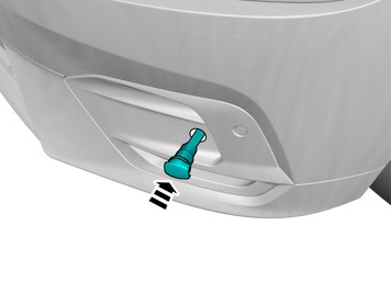
| | Disconnect the connector. |
| | |
| | |
|  | | IMG-450201 |
|
| | |
|  | | IMG-450205 |
|
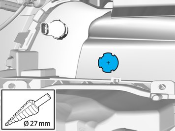
| | Measure and mark out the centre. Use a drill with the stated size |
|  | | IMG-448275 |
|
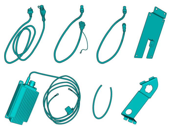
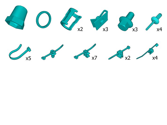
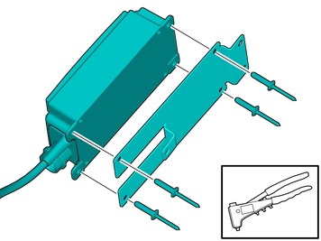
| | Assemble components that come with the accessory kit. |
|  | | IMG-466885 |
|
| | |
|  | | IMG-450245 |
|
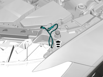
| | Install components that come with the accessory kit. Tighten the nut. Use hands only. |
|  | | IMG-450246 |
|
| | |
|  | | IMG-450250 |
|
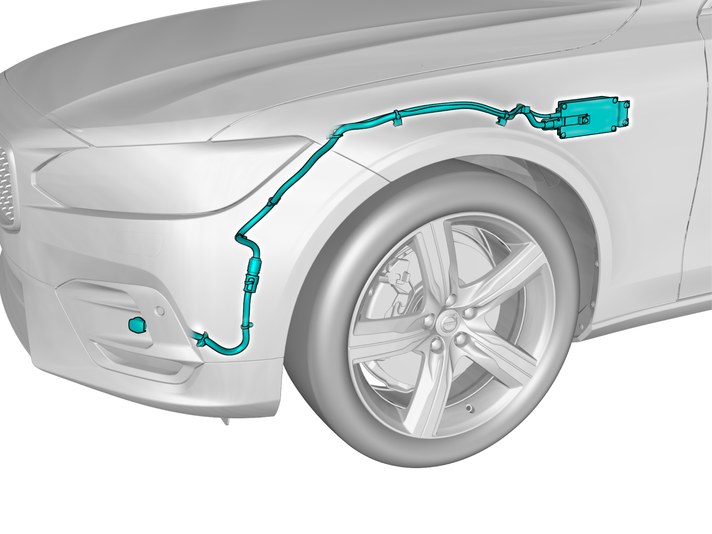
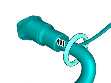
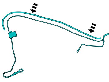
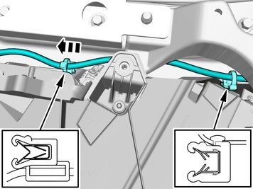
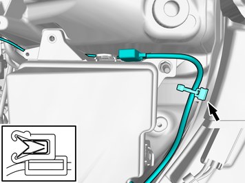
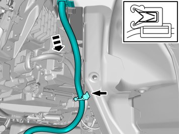
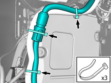
| | Position/route the cable as illustrated. Install the cable. Use a cable tie |
|  | | IMG-448511 |
|
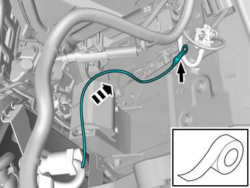
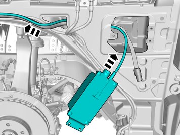
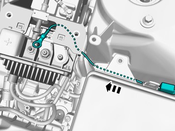
| | Position/route the cable as illustrated. Use tape and attach the wire to the existing wiring harness. |
| | |
|  | | IMG-448507 |
|
| | Reinstall the removed part. Reinstall the screws. |
|  | | IMG-448509 |
|
| | Reinstall the removed part. |
| | | IMG-448504 |
|
| | Reinstall the removed part. Reinstall the screws. |
|  | | IMG-448510 |
|
| | Reinstall the removed part. |
| | |
|  | | IMG-448290 |
|
| | Use detail according to image. |
|  | | IMG-448386 |
|
| | |
|  | | IMG-448389 |
|
| | |
| | Vehicles with diesel engines |
|  | | IMG-448408 |
|
| | |
| | |
|  | | IMG-400004 |
|
| | Note!
Images are displayed without front fender. |
|
|  | | IMG-448418 |
|
| | |
|  | | IMG-448421 |
|
| | Install components that come with the accessory kit. |
|  | | IMG-449536 |
|
| | Assemble components that come with the accessory kit. |
|  | | IMG-448427 |
|
| | Assemble components that come with the accessory kit. |
|  | | IMG-448450 |
|
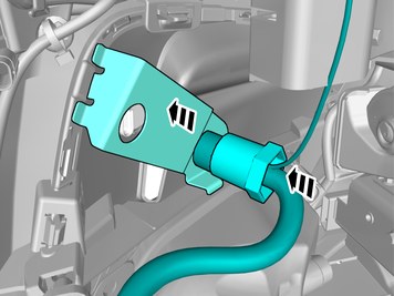
| | Pull the wiring harness through. |
|  | | IMG-440310 |
|
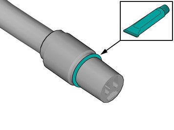
| | Lubricate the O-ring. Use: 1161427, Low temperature grease
|
|  | | IMG-448458 |
|
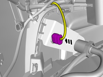
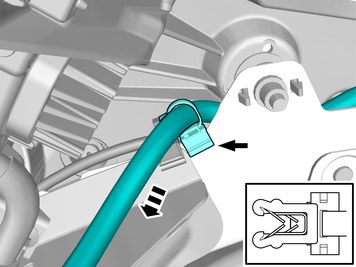
| | Connect the cable. Install the catch. |
|  | | IMG-448469 |
|
| | |
|  | | IMG-449525 |
|
| | |
|  | | IMG-448470 |
|
| | |
|  | | IMG-448488 |
|
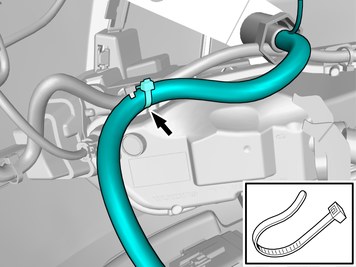
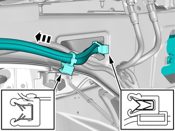
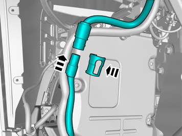
| | Caution!
Do not attach the clamb to the washer hose. |
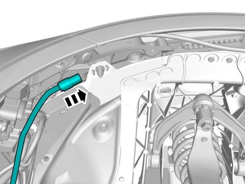
Position/route the cables as illustrated. Install the cables. Use a cable tie |
|  | | IMG-448491 |
|
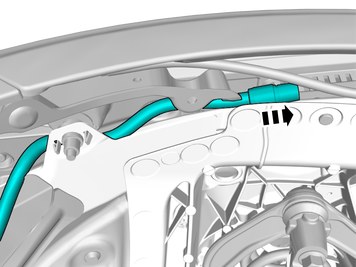
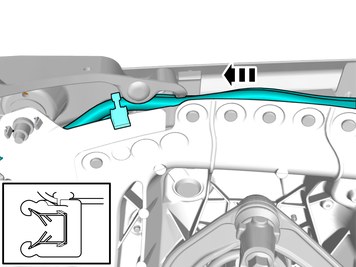
| | Position/route the cables as illustrated. Install the cables. Use a cable tie |
|  | | IMG-448495 |
|
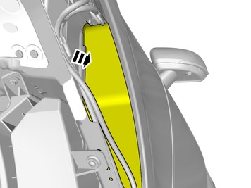
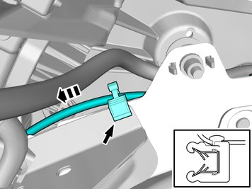
| | Position/route the cable harness as illustrated. Install the wiring harness. Use a cable tie |
|  | | IMG-449529 |
|
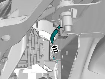
| | Pull the wiring harness through. Lower the vehicle. |
|  | | IMG-449534 |
|
| | Pull the wiring harness through. |
|  | | IMG-449545 |
|
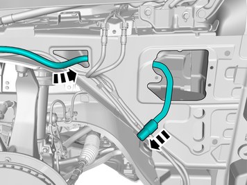
| | Position/route the cable harness as illustrated. Install the wiring harness. Use a cable tie |
|  | | IMG-449615 |
|
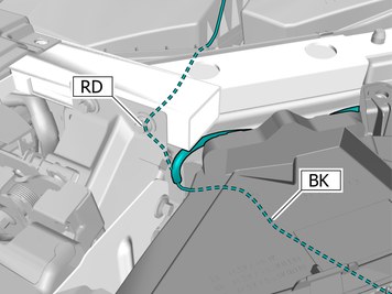
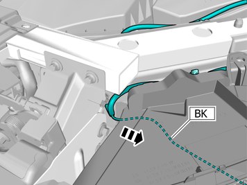
| | Caution!
Ensure that the wire or wiring harness cannot rub against adjacent components. |
RD = Red BK = Black |
|  | | IMG-449562 |
|
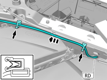
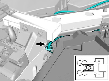
| | Position/route the cable as illustrated. Install the cable. Use a cable tie |
|  | | IMG-449560 |
|
| | Position/route the cable as illustrated. Install the cable. Use a cable tie |
|  | | IMG-449555 |
|
| | Position/route the cable as illustrated. |
|  | | IMG-449557 |
|
| | |
|  | | IMG-449558 |
|
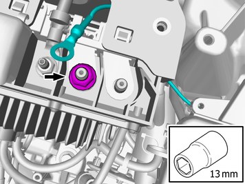
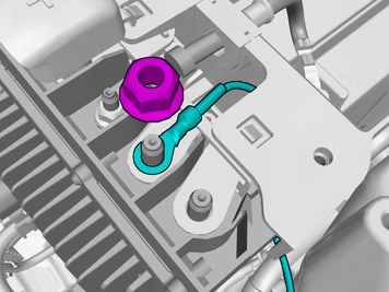
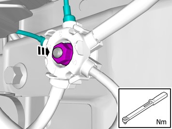
| | Connect the prerouted cable. Install the nut.
Tightening torque: Nut (M8), to BCSM
, 24 Nm
|
|  | | IMG-449616 |
|
| | |
|  | | IMG-449617 |
|
| | Install the wiring harness. Use a cable tie Raise the car. |
|  | | IMG-449636 |
|
| | |
|  | | IMG-466585 |
|
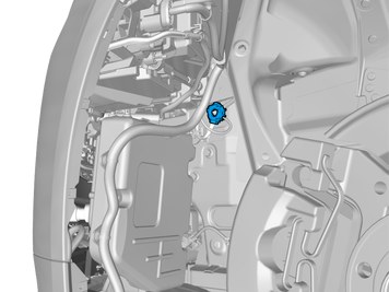
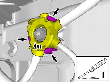
| | Release the catches. Loosen the marked detail. |
|  | | IMG-466592 |
|
| | |
|  | | IMG-449730 |
|
| | |
|  | | IMG-449728 |
|
| | Connect the prerouted cables. |
|  | | IMG-449695 |
|
| | Install the marked component. Ensure that all clips engage. |
|  | | IMG-449696 |
|
| | Install the nut.
Tightening torque: M6
, 10 Nm
|
|  | | IMG-448496 |
|
| | Position/route the cable as illustrated. Install the cable. Use a cable tie |
|  | | IMG-449600 |
|
| | Position/route the cable as illustrated. Install the cable. Use a cable tie |
| | | IMG-440310 |
|
| | Lubricate the O-ring. Use: 1161427, Low temperature grease
|
|  | | IMG-449601 |
|
| | Connect the cable. Install the catch. |
|  | | IMG-449602 |
|
| | Position/route the cable as illustrated. Install the cable. Use a cable tie |
| | |
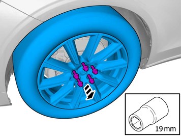
| | Reinstall the removed parts in reverse order. |
| 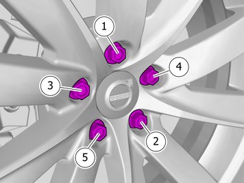 | | IMG-405228 |
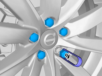
|
| |
Tightening torque: Aluminum wheel rim to wheel hub
Stage 1:
4 Nm
Stage 2:
50 Nm
Stage 3:
140 Nm
|
|  | | IMG-400003 |
|
| | Reinstall the battery's negative cable. |