| | |
|  | | IMG-316263 |
|
| | |
|  | | J8000359 |
|
| | |
|  | | J8601130 |
|
| | |
|  | | IMG-265763 |
|
| | |
|  | | J8601087 |
|
| | |
|  | | J8601084 |
|
| | |
|  | | J8903376 |
|
| | |
|  | | J8601086 |
|
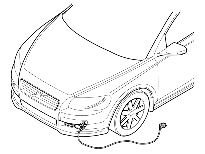
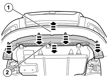
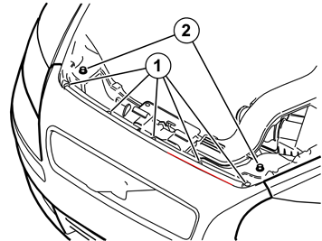
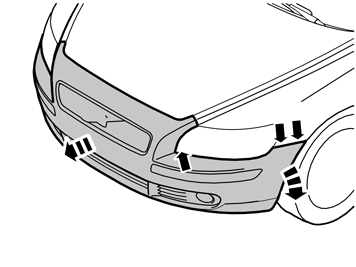
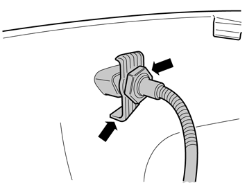
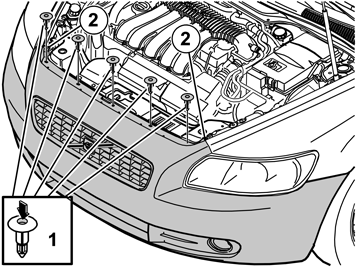
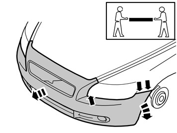
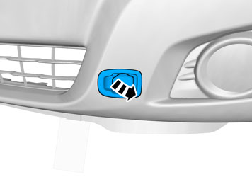
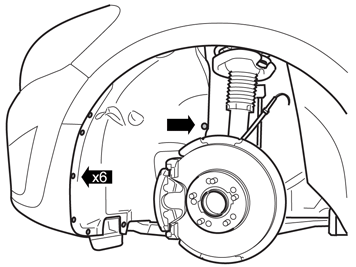
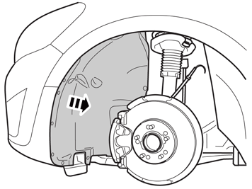
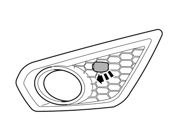
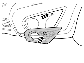
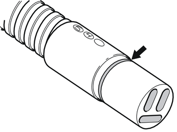
| | Detach the ends of the bumper shell on the left and right-hand sides. Grasp the end of the bumper shell inside the fender liner. Carefully pull the end of the bumper shell so that the two catches on the inside release. Remove the bumper cover and air baffle. Pull the bumper cover and air baffle forwards until the remaining catches under the lamps release. Disconnect the connectors for the fog lamps and parking assistance if applicable.
|
|  | | IMG-265777 |
|
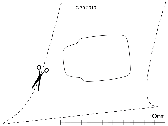
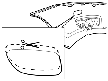
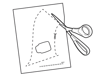
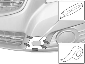
| | Cut out the template by cutting along the outer edges of the dotted and solid line. place the template with the dotted section on the existing marking (perforation) on the bumper. Mark according to the new, slightly recessed marking. Cut off the upper dotted section of the template and finish the new marking all the way around.
|
|  | | IMG-265778 |
|
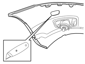
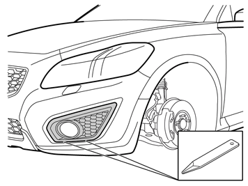
| | Using a sharp knife, first make a thin cut along the edges of the new marking inside of the bumper cover. Then carefully cut out the bumper cover hole. Cut off the upper dotted section of the template and finish the new marking all the way around.
Warning!
Cut carefully. It is easy to slip with the knife and move outside the markings. |
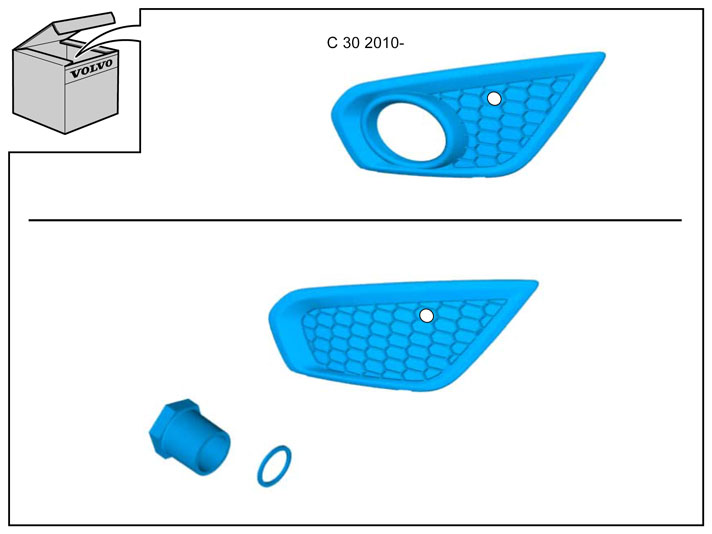
Install the protective cover for the front engine block heater socket from the kit. Check that it aligns. Adjust the hole using a knife or file as necessary. Smooth off the hole edges. Remove any swarf.
|
|  | | IMG-265779 |
|
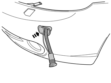
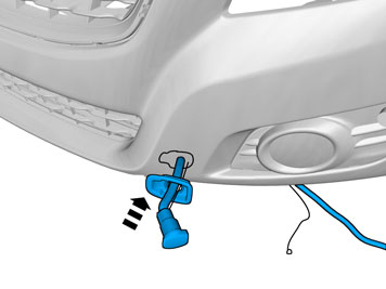
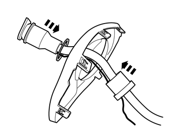
| | Take the protective cover from the kit and press it into the hole cut in the bumper cover. Take the cable for the front engine block heater socket with ground lead from the kit and thread them through the protective cover.
|
|  | | IMG-265781 |
|
| | |
|  | | IMG-265782 |
|
| | |
|  | | IMG-332924 |
|
| | |
|  | | IMG-332914 |
|
| | |
|  | | IMG-332916 |
|
| | Position the templates following the curves of the surface between the lower grille and panel for the fog lamps and tape it according to the image. Take a sharp knife. First make a thin cut along the edges of the inside of the template. This provides a groove to follow. Then cut carefully out of the bumper cover.
Warning!
Cut carefully. It is easy to slip with the knife and move outside the template. |
Remove the template. Install the protective cover for the front engine block heater socket from the kit. Check that it aligns. Adjust the hole using a knife or file as necessary. Smooth off the hole edges. Remove any swarf.
|
| | | J8601130 |
|
| | |
|  | | J8601131 |
|
| | |
|  | | IMG-225652 |
|
| | |
|  | | IMG-332933 |
|
| | |
|  | | IMG-227800 |
|
| | |
|  | | IMG-225649 |
|
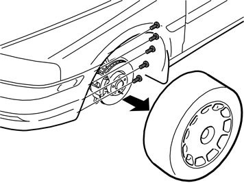
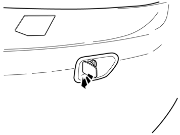
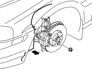
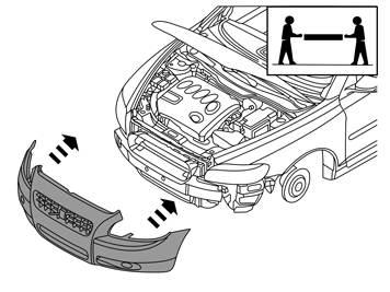
| | Detach the right and left-hand ends of the bumper. Grip the bumper from the inside and pull it forward in order to detach the two holders under the headlamps. Remove the bumper, unplug the connectors for the fog lamps and place the bumper on a surface that does not damage the paintwork.
Hint
This procedure is easier carried out by two people. |
|
|  | | IMG-332938 |
|
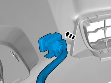
| | Press the protective cover (from the kit) into place in the hole cut in the bumper cover. Insert the cable for the front engine block heater socket together with the ground lead from the kit through the protective cover.
|
|  | | IMG-332939 |
|
|  | | IMG-332943 |
|
| | Illustration A Illustration B |
|  | | IMG-225646 |
|
| | |
|  | | IMG-332918 |
|
| | |
|  | | IMG-331946 |
|
| | |
|  | | IMG-331947 |
|
| | |
|  | | IMG-331948 |
|
| | |
|  | | IMG-332920 |
|
| | |
|  | | IMG-331989 |
|
|  | | IMG-331990 |
|
| | Illustrations A and B Note!
The washer must be positioned as illustrated. |
|
|  | | IMG-331991 |
|
| | |
|  | | IMG-225640 |
|
| | Applies to all car models where the bumper cover is removed Reinstall the bumper cover. Use the five clips and the two screws at the top edge. Ensure that the air baffle is correctly positioned in its mounting. Press in so that the clips under the headlamps fasten. Reconnect the connectors for the fog lamps and parking assistance if applicable.
Hint
This procedure is easier carried out by two people. |
|
|  | | J2900313 |
|
| | |
|  | | IMG-360291 |
|
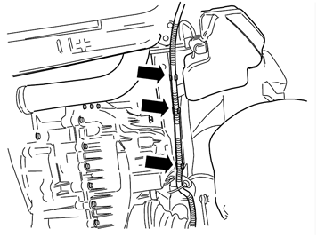
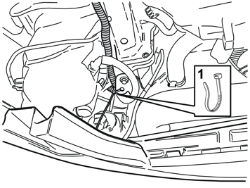
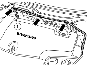
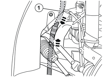
| | Route the front intake cable from the front edge of the washer fluid reservoir, along the bottom edge of the front member and over the drive shaft. Route the cable a bit into the engine compartment. Press the cable into the previously installed clips.
|
|  | | IMG-339147 |
|
| | |
|  | | IMG-339151 |
|
| | |
|  | | J2900297 |
|
| | |
|  | | J2900298 |
|
| | Drill a Ø4 mm (5/32) hole for the ground lead, on the outside of the left-hand front member, approximately as illustrated. Treat the edges of the holes using a rust-proofing agent.
|
|  | | J2900299 |
|
| | |
|  | | IMG-232644 |
|
| | |
|  | | IMG-339141 |
|
| | |
|  | | IMG-232645 |
|
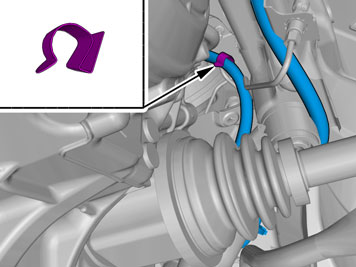
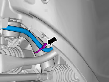
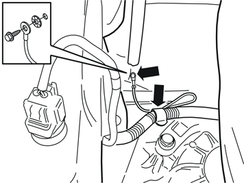
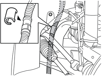
| | Press the front intake cable into the clips. Guide down the cable at point (1) and route down through the engine compartment down to the strut in the right link arm mounting. Secure the cable, from the top of the engine compartment and down, using a cable tie at the existing cable harness.
Note!
Do not clamp the cable directly to AC pipes, fuel lines, brake pipes or power steering hoses and pipes. Make sure the cable does not chafe against sharp edges or moving parts in the engine compartment. |
|
|  | | IMG-339146 |
|
| | |
|  | | D3601932 |
|
| | Note!
Do not get any grease on the surfaces of the connector. |
|
|  | | J2900302 |
|
| | Applies to cars where the engine block heater and passenger compartment connector socket are installed at the same time |
|  | | J2900296 |
|
| | Cable to engine block heater Cable to passenger compartment connector Cable from front intake
|
|  | | J2900303 |
|
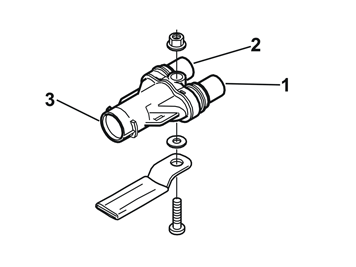
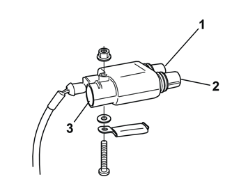
| | Tighten the timer relay at the bracket (purchased separately) in the position illustrated. Use the screw, toothed washer and nut from the kit. The bracket must be parallel to the length of the timer relay. Connect the connector on the long cable harness (from the kit) to the timer relay.
Press the rubber plug (1), part no. 346509, (purchased separately) into place on the free socket in the timer relay. Use butyl tape to secure the rubber plug. Position (2) cable for the engine block heater Position (3) cable from the front engine block heater socket.
|
|  | | J2900304 |
|
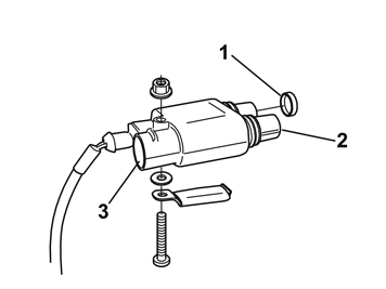
| | Tighten the timer relay at the bracket (purchased separately) in the position illustrated. Use the screw, toothed washer and nut from the kit. The bracket must be parallel to the length of the timer relay. Connect the connector on the long cable harness (from the kit) to the timer relay. Connect the connector on the long cable harness (from the kit) to the timer relay.
Position (1) cable for the passenger compartment socket Position (2) cable for the engine block heater Position (3) cable from the front engine block heater socket.
|
|  | | J2900292 |
|
| | Connect the short cable from the kit to the engine block heater, to the routed cable (1) from the front socket. (When fitting junction connector/timer relay at the same time, the cable from the front socket is connected to the single outlet on the junction connector/timer relay instead. Refer to the installation instructions for passenger compartment socket/timer relay). Firmly press the cable junction together.
|
|  | | J2900293 |
|
| | |
|  | | J2900294 |
|
| | |
|  | | IMG-339016 |
|
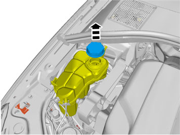
| | Note!
Be prepared to collect liquid that runs out. |
|
|  | | IMG-316564 |
|
| | |
|  | | IMG-316566 |
|
| | |
|  | | IMG-316568 |
|
| | |
|  | | IMG-316571 |
|
| | |
|  | | IMG-316583 |
|
| | |
|  | | IMG-214121 |
|
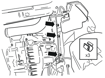
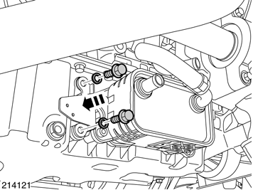
| | Note!
The screws are self-tapping so it may be slow inserting them. Make sure that the screws are centred straight into the holes, so that the screw heads are flat against the bracket. |
|
| 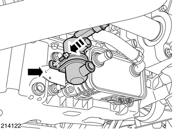 | | IMG-214122 |
|
| | |
|  | | IMG-316743 |
|
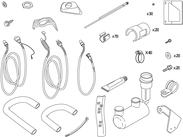
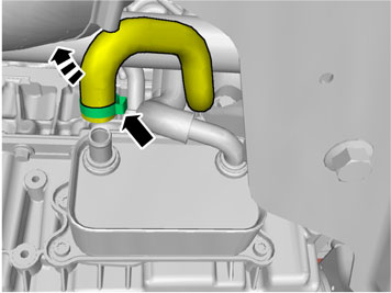
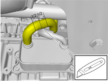
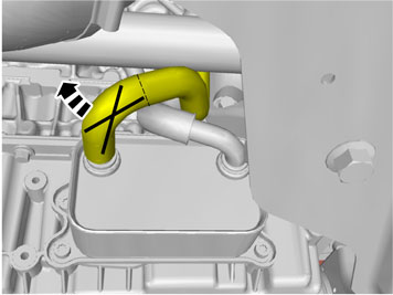
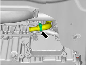
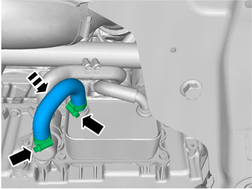
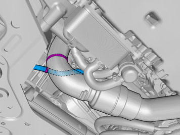
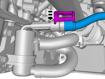
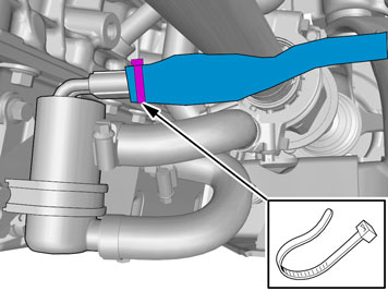
| | Get junction cable and two hose clamps from the kit. Install the hose between the earlier installed junction nipple and the upper connection in the engine heater. Tighten the clamps securely. Make sure that the hoses do not rub against the drive shaft or hose clamps.
|
|  | | IMG-316744 |
|
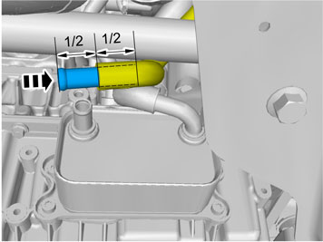
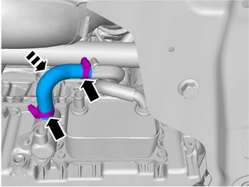
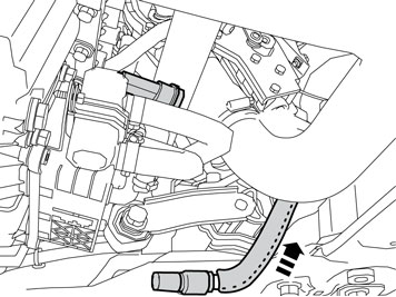
| | Get the last junction hose and the two remaining hose clamps from the kit. Connect the junction hose between the remaining connections in the engine heater and the oil cooler. Tighten the clamps securely.
Caution!
Ensure that the hoses do not catch the charge air pipe. |
|
|  | | IMG-235624 |
|
| | |
|  | | IMG-340340 |
|
| | |
|  | | IMG-340339 |
|
| | |
|  | | IMG-340337 |
|
| | Connect the short electrical cable (which was routed earlier) to the engine block heater. Press it firmly into the engine block heater connection. Press in a locking sleeve from the kit over the cable splice.
|
|  | | IMG-340336 |
|
| | |
| | Reinstall the detached components in reverse order. Fill with coolant and run the engine to operating temperature. |