| | |
| | Read through all of the instructions before starting installation. Notifications and warning texts are for your safety and to minimise the risk of something breaking during installation. Ensure that all tools stated in the instructions are available before starting installation. Certain steps in the instructions are only presented in the form of images. Explanatory text is also given for more complicated steps. In the event of any problems with the instructions or the accessory, contact your local Volvo dealer.
|
| | |
| | When installing, the car must retain a temperature of 20 degrees C. |
| | |
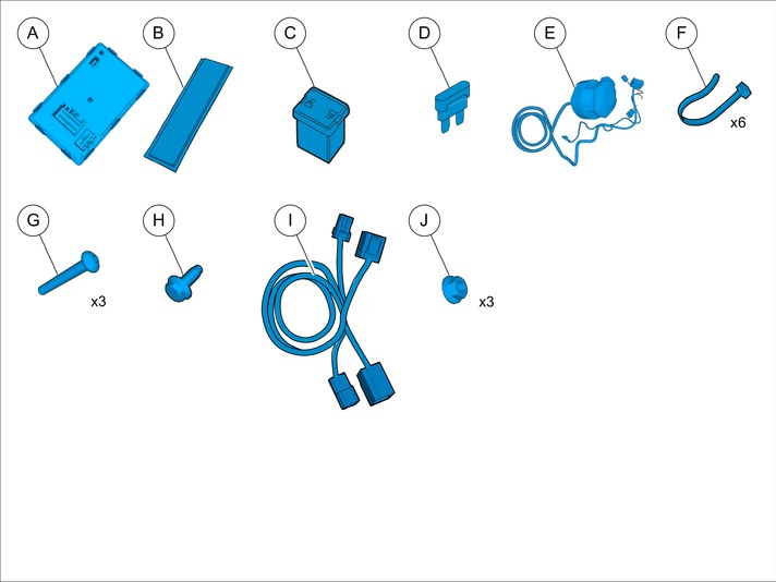
|  | | IMG-363036 |
|
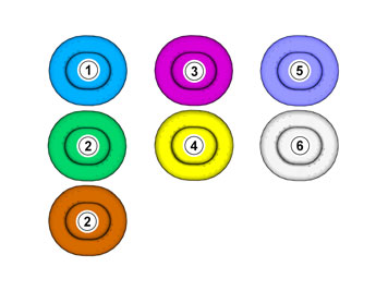
| | Note!
This colour chart displays (in colour print and electronic version) the importance of the different colours used in the images of the method steps. |
Used for focused component, the component with which you will do something. Used as extra colors when you need to show or differentiate additional parts. Used for attachments that are to be removed/installed. May be screws, clips, connectors, etc. Used when the component is not fully removed from the vehicle but only hung to the side. Used for standard tools and special tools. Used as background color for vehicle components.
|
|  | | IMG-245980 |
|
| | Set the ignition key to position 0. |
| | |
|  | | IMG-264423 |
|
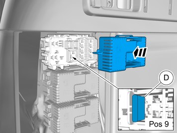
| | |
|  | | IMG-264424 |
|
| | |
|  | | IMG-361641 |
|
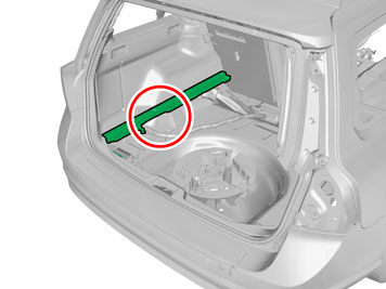
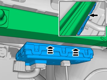
| | Remove the part carefully |
|  | | IMG-268004 |
|
| | |
|  | | IMG-268005 |
|
| | |
| | |
|  | | IMG-356021 |
|
| | |
|  | | IMG-356033 |
|
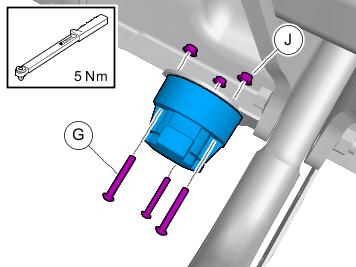
| |
Tightening torque: M5
, 5 Nm
|
|  | | IMG-264524 |
|
| | |
|  | | IMG-264525 |
|
| | |
|  | | IMG-361518 |
|
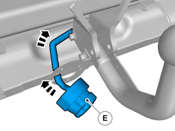
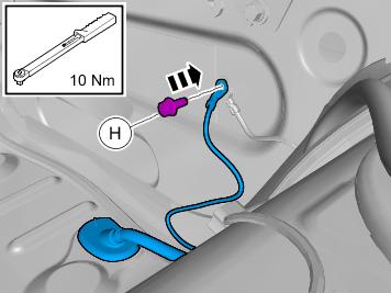
| | Ground connection
Tightening torque: M6
, 10 Nm
|
|  | | IMG-265733 |
|
| | |
| | |
| 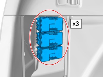 | | IMG-384843 |
|
| | |
| | |
| 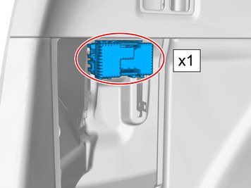 | | IMG-384844 |
|
| | |
| | |
|  | | IMG-264443 |
|
| | |
|  | | IMG-264444 |
|
| | |
|  | | IMG-360395 |
|
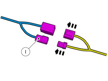
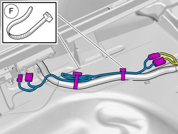
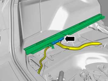
| | Route the cable harness to the existing cable harness. |
|  | | IMG-360376 |
|
| |
Use special tool: T9512932, Tension spring
Use tape Pull the wiring through. |
|  | | IMG-360381 |
|
| | Caution!
Ensure that the wire or wiring harness cannot rub against adjacent components. |
Route the cable harness to the existing cable harness. |
|  | | IMG-340349 |
|
| | |
|  | | IMG-372406 |
|
| | Use: Interior trim remover
|
|  | | IMG-360386 |
|
| | |
|  | | IMG-264451 |
|
| | |
|  | | IMG-385161 |
|
| | |
| | |
| | | IMG-384844 |
|
| | |
|  | | IMG-338941 |
|
| | |
|  | | IMG-338943 |
|
| | |
|  | | IMG-361516 |
|
| | Route the cable harness to the existing cable harness. |
|  | | IMG-360396 |
|
| |
Use special tool: T9512932, Tension spring
Use tape Pull the wiring through. |
|  | | IMG-361514 |
|
| | Caution!
Ensure that the wire or wiring harness cannot rub against adjacent components. |
|
| | | IMG-340349 |
|
| | |
| | | IMG-372406 |
|
| | Use: Interior trim remover
|
|  | | IMG-372409 |
|
| | Connect the prerouted cable. |
|  | | IMG-360399 |
|
| | |
|  | | IMG-338948 |
|
| | |
|  | | IMG-384689 |
|
| | |
| | |
|  | | IMG-361501 |
|
| | |
|  | | IMG-360217 |
|
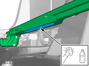
| | Use: 1161721, Isopropanol
Wipe dry. |
|  | | IMG-360218 |
|
| | Use: 1161721, Isopropanol
Wipe dry. |
|  | | IMG-356181 |
|
| | |
|  | | IMG-360227 |
|
| | Remove the protective film. |
|  | | IMG-384588 |
|
| | When installing Velcro tape the surface must maintain a temperature of at least +20 ° C (68°F). |
|  | | IMG-360226 |
|
| | Fold the insulation to one side. |
|  | | IMG-360221 |
|
| | Locate the pre-routed connectors. |
|  | | IMG-384634 |
|
| | Connect the cable harness. |
|  | | IMG-384757 |
|
| | Route the cable harness to the existing cable harness. Attach any excess wire to the wiring harness. |
|  | | IMG-384534 |
|
| | Note!
Make sure to follow the sequence indicated. |
Connect the connectors. |
|  | | IMG-384589 |
|
| | Remove the protective film. |
|  | | IMG-384559 |
|
| | Caution!
Ensure that the wire or wiring harness cannot rub against adjacent components. |
Place the component where indicated in the graphic. |
|  | | IMG-385298 |
|
| | Place the component where indicated in the graphic. |
| | | IMG-338941 |
|
| | |
|  | | IMG-384607 |
|
| | |
| | |
|  | | IMG-242268 |
|
| | Download software (application) for the accessory's function according to the service information in VIDA. Order and download software according to: 30744326
|
| | |
|  | | IMG-348017 |
|
| | Note!
To activate the trailer module (TRM) at least two light sources (lamps) must be connected. This can be done by connecting test equipment for the trailer connector, or a trailer. |
Note!
The trailer module (TRM) must be programmed with correct software to function correctly. |
Left indicator lamp Fog tail lamps. Ground connection Right indicator lamp Right position lamp Brake light Left position lamp Back-up lamp Battery voltage, constant Battery voltage, ignition on Ground connection Not connected Ground connection
|
| | |
| | Reinstall the removed parts in reverse order. |