| | |
|  | | IMG-352652 |
|
| | |
|  | | IMG-352653 |
|
| | |
|  | | IMG-352654 |
|
| | |
| | | IMG-352653 |
|
| | |
|  | | IMG-352655 |
|
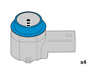
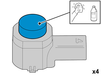
| | Caution!
Protect the connections' contact surfaces against paint. |
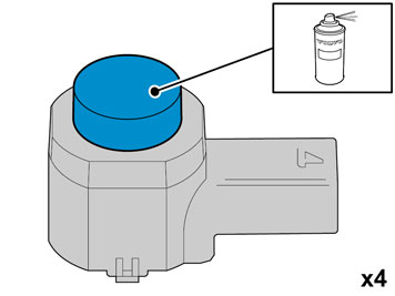
Paint the sensors in the same colour code as the vehicle. Use Volvo Touch-up paint. (Only use base coat.) Use: Volvo 2-K Varnish, P/N: 31335447
Note!
Also read the instructions on the spray can. |
|
|  | | IMG-352658 |
|
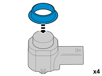
| | Caution!
The paint must have dried after the first application. |
|
|  | | IMG-332193 |
|
| | Note!
Wait at least one minute before unplugging the connectors or removing other electrical equipment. |
|
|  | | IMG-349804 |
|
| | |
|  | | IMG-349806 |
|
| | |
|  | | IMG-345282 |
|
| | |
|  | | IMG-354293 |
|
| | Cars with manual transmissions |
|  | | IMG-347222 |
|
| | |
|  | | IMG-293006 |
|
| | Cars with automatic transmissions |
|  | | IMG-293007 |
|
| | |
|  | | IMG-292804 |
|
| | |
|  | | IMG-340599 |
|
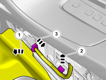
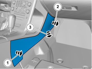
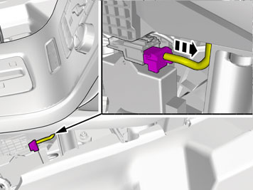
| | Fold back the mat. Unhook the cable harness clips. Unplug the connector.
|
|  | | IMG-353601 |
|
| | |
|  | | IMG-353602 |
|
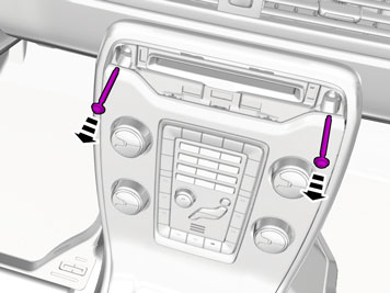
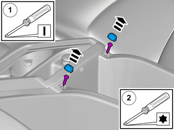
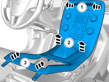
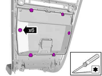
| | Remove the covers. Remove the screws.
|
|  | | IMG-292826 |
|
| | Applies to vehicles with the 4-C system |
|  | | IMG-345317 |
|
| | |
|  | | IMG-349826 |
|
| | Caution!
Be careful to not damage the hooks. |
|
|  | | IMG-345295 |
|
| | |
|  | | IMG-345296 |
|
| | |
|  | | IMG-340638 |
|
| | |
|  | | IMG-353570 |
|
| | |
|  | | IMG-259683 |
|
| | |
|  | | IMG-259684 |
|
| | |
|  | | IMG-259685 |
|
| | |
|  | | IMG-273303 |
|
| | |
|  | | IMG-273304 |
|
| | Carefully pull off the ends of the bumper cover on both sides. They are secured by hooks at the top edge of the ends and at the lower edge of the rear lights. Pull off the bumper cover from the rear of the body, it is positioned in seven guides at the top edge of the long side.
Note!
It is recommended that two people carry out this step to prevent damaging the bumper cover. |
Place the bumper cover on a suitable surface.
|
|  | | IMG-283023 |
|
| | |
|  | | IMG-283024 |
|
| | |
|  | | IMG-273309 |
|
| | |
|  | | IMG-283025 |
|
| | |
|  | | IMG-283026 |
|
| | |
|  | | IMG-283027 |
|
| | |
|  | | IMG-283028 |
|
| | |
|  | | IMG-283030 |
|
| | |
|  | | IMG-283031 |
|
| | |
|  | | IMG-273313 |
|
| | |
|  | | IMG-283032 |
|
| | |
| | | IMG-283026 |
|
| | |
|  | | IMG-283033 |
|
| | |
| | | IMG-283028 |
|
| | |
|  | | IMG-261414 |
|
| | |
|  | | IMG-273316 |
|
| | |
| | |
|  | | IMG-273317 |
|
| | |
|  | | IMG-273318 |
|
| | |
|  | | IMG-273319 |
|
| | |
|  | | IMG-273320 |
|
| | |
|  | | IMG-273321 |
|
| | |
|  | | IMG-273322 |
|
| | |
|  | | IMG-273323 |
|
| | |
|  | | IMG-273324 |
|
| | |
|  | | IMG-247283 |
|
| | |
|  | | IMG-247284 |
|
| | |
|  | | IMG-283034 |
|
| | Note!
The adhesive must be above the level for the tape. |
Caution!
The adhesive must not come into contact with the tape. |
Use special tool: 9510250 Adhesive gun. Use: 1161730 Mixing pipe. Use: 9511027 Adhesive. |
|  | | IMG-247286 |
|
| | Install the centering tool in the holder. Install the tool on the bumper cover. Press the holder towards the casing, but only at the places where there is tape. Hold the holder securely when removing the centering tool. The holder must be installed horizontally and in line with the bumper cover. Repeat the steps until all four holders are in place.
|
|  | | IMG-247287 |
|
| | |
|  | | IMG-247288 |
|
| | Note!
The large gray connector must protrude from the right-hand side of the bumper cover. |
|
|  | | IMG-273326 |
|
| | |
|  | | IMG-273330 |
|
| | Note!
It is recommended that two people carry out this step to prevent damaging the bumper cover. |
|
|  | | IMG-273331 |
|
| | Press the bumper's hooks in at the rear edge. Press all the hooks for the ends into the body. Reinstall the screws on the front edges of the bumper casing. Reinstall the plastic nuts at the lower edge.
|
|  | | IMG-242268 |
|
| | |