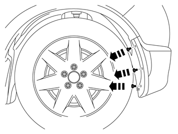
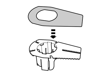
|  | | IMG-344336 |
|
| | |
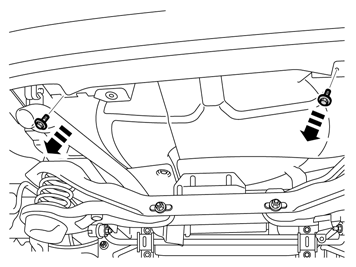
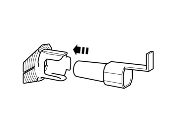
|  | | IMG-352653 |
|
| | |
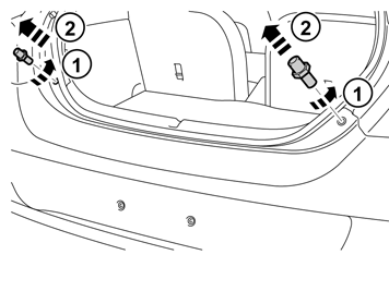
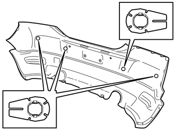
|  | | IMG-352654 |
|
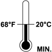
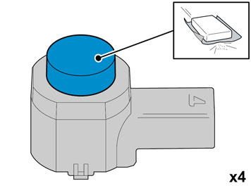
| | Carefully mat down the surface. Use Glasspaper, grade P1000. |
| | | IMG-352653 |
|
| | |
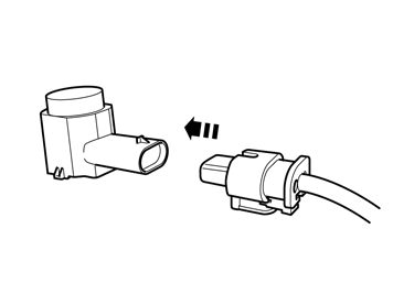
|  | | IMG-352655 |
|
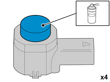
| | Caution!
Protect the connections' contact surfaces against paint. |
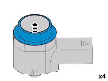
Paint the sensors in the same colour code as the vehicle. Use Volvo Touch-up paint. (Only use base coat.) use Volvo 2-K Varnish. P/N: 31335447.
Note!
Also read the instructions on the spray can. |
|
|  | | IMG-352658 |
|
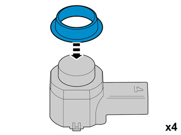
| | Caution!
The paint must have dried after the first application. |
|
|  | | IMG-245980 |
|
| | |
|  | | IMG-254256 |
|
| | |
|  | | IMG-240963 |
|
| | |
|  | | IMG-240964 |
|
| | |
|  | | IMG-240965 |
|
| | |
|  | | IMG-240972 |
|
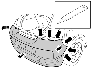
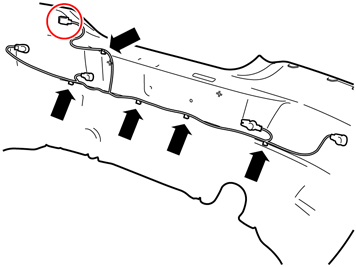
| | Remove the bumper cover from the body by carefully prying off the ends using a weatherstrip tool. Pull the cover from the tail lamp and rear edge of the wing on each side. It is secured by four catches at the tail lamp and four at the rear edge of the rear wing. Pull the bumper cover straight back.
|
|  | | IMG-240974 |
|
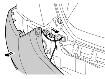
| | Disconnect the connector for the license plate lighting on the left-hand side. Place the bumper cover on a protective surface. Remove the pieces of tape.
|
|  | | IMG-254257 |
|
| | |
|  | | IMG-254258 |
|
| | |
|  | | IMG-254259 |
|
| | |
|  | | IMG-254260 |
|
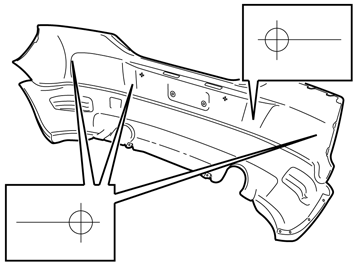
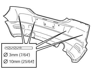
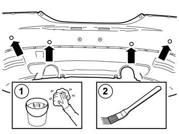
| | Clean the inside of the bumper cover using a mild soap solution. Clean around the holes and the markings using isopropanol. Allow to dry. Apply a thin layer of activator, part no. 8637076, to the cleaned surfaces and let dry for approx. 10 min.
|
|  | | IMG-254261 |
|
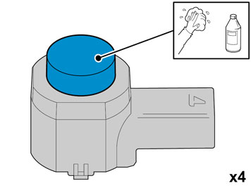
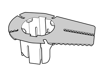
| | Take the 4 holders from the kit. Clean the surfaces as illustrated using isopropanol. Allow to dry. Apply a thin and even layer of activatorpart no. 8637076, on the cleaned surfaces and let dry for at least 10 min.
|
|  | | IMG-250925 |
|
| | |
|  | | IMG-250926 |
|
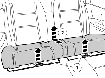
| | Fold the central arm rest forward. Remove the central arm rest by grasping each end and pulling upwards until it releases at the rear edge from the backrest's lugs (1). Then pull forwards until the holders (2) on the sides of the backrest have slid out of the corresponding cut-out (3) in the central arm rest.
|
|  | | IMG-250927 |
|
| | |
|  | | IMG-250928 |
|
| | |
|  | | IMG-250929 |
|
| | |
|  | | IMG-250930 |
|
| | |
|  | | IMG-251368 |
|
| | |
|  | | IMG-251369 |
|
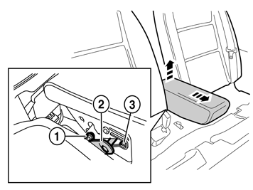
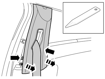
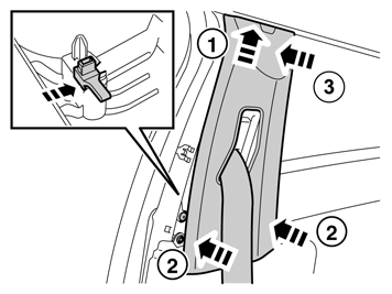
| | Unhook the safety clip from the panel. Angle out the panel at the lower edge, and then unhook it at the upper edge so that the upper clip releases.
|
|  | | IMG-251370 |
|
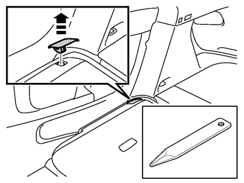
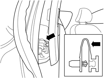
| | Remove the screw from the right-hand panel in the rear seat. Carefully pull off the panel from the body side. It is secured by ten clips on the inside. Unhook it from the sill at the front edge.
|
|  | | IMG-240957 |
|
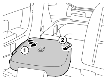
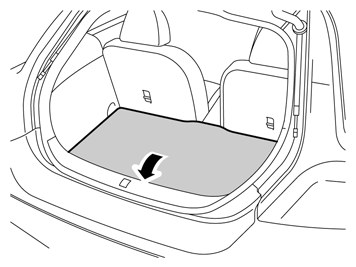
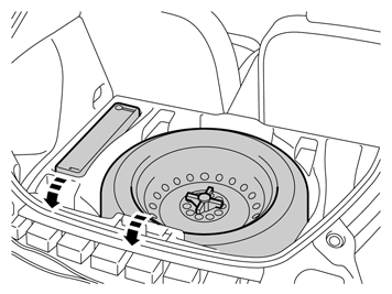
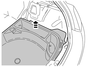
| | Lift up the floor hatch at the rear edge. Pull it backwards so that it detaches at the front edge. Turn the cover and lift out.
|
|  | | IMG-241183 |
|
| | |
|  | | IMG-253759 |
|
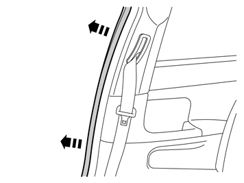
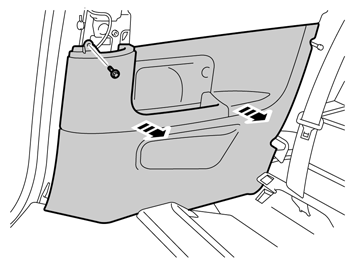
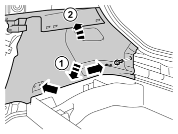
| | Remove the clips at the rear edge of the right-hand rear side panel. Carefully pull the side panel off, starting at the front edge/upper edge and then straight back until all clips at the top edge have released. Fold the panel inwards. Release it from the anchorage eyelets and lift it out of the load floor support.
|
|  | | IMG-241184 |
|
| | |
|  | | IMG-241200 |
|
| | |
|  | | IMG-246008 |
|
| | |
|  | | IMG-246009 |
|
| | |
|  | | IMG-254273 |
|
| | Note!
The holders must be mounted turned against the holes as illustrated. The holders must also be horizontal and in line with the bumper cover. |
|
|  | | IMG-247287 |
|
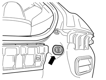
| | Note!
The large grey connector must be on the right-hand side. (also see next point) |
|
|  | | IMG-254274 |
|
| | |
|  | | IMG-254275 |
|
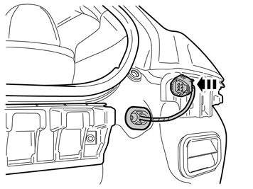
| | Note!
Vehicles with towbar wiring, see points for "Applies to vehicles with towbar wiring". |
|
|  | | IMG-254276 |
|
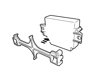
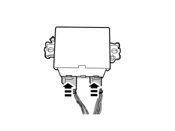
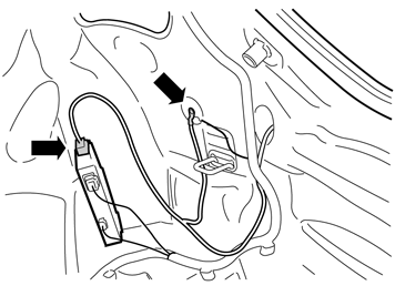
| | Take the cable harness with the rubber grommet from the kit. Pull the cable harness through the hole in the cargo compartment. Place the rubber grommet in position. Press the connector on the plastic bracket.
|
|  | | IMG-254277 |
|
| | |
|  | | IMG-254278 |
|
| | Note!
Ensure that the connector's catches click and are properly secured. |
|
|  | | IMG-254279 |
|
| | |
|  | | IMG-254280 |
|
| | |
|  | | IMG-254281 |
|
| | |
|  | | IMG-254282 |
|
| | |
|  | | IMG-346988 |
|
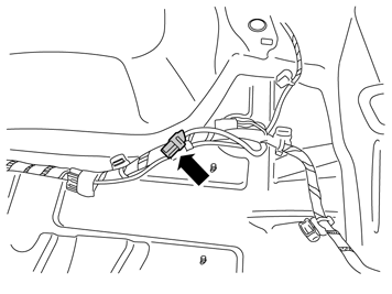
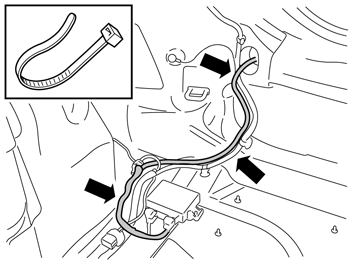
| | Applies to vehicles with tow bar wiring. Detach the towbar wiring connector from the Trailer Module (TRM). Disconnect the ground lead.
|
|  | | IMG-222068 |
|
| | |
|  | | IMG-254283 |
|
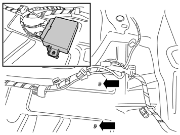
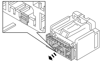
| | Applies to vehicles with tow bar wiring. Disconnect all terminals from the connector.
Note!
Note the location of the cables in the connector. |
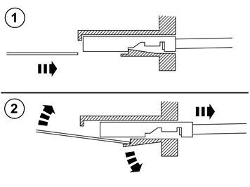
Use special tool 9512810 or 9512632. Insert the tool in the connector and release the locking. Pull out the cable with terminal. Pull out the cable harness through the rubber grommet. Remove the rubber grommet, it shall not be re-used. |
|  | | IMG-254284 |
|
| | Applies to vehicles with tow bar wiring. Cut off the free rubber spout (1) on the rubber grommet of the PAS wiring. Thread the tow bar wiring through. Lubricate the tow hitch wiring using Volvo's low temperature grease and thread the tow bar wiring (2) through. Connect the terminals to the connector. Secure the locking and connect to the trailer module (TRM).
|
|  | | IMG-254285 |
|
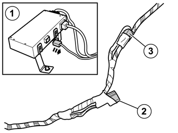
| | The existing 5 pin green connector is connected to the trailer module (TRM) (1). Detach the connector to the control module and connect it to the PAS wiring (2). Disconnect the 5 pin green connector (3) that is taped to the wiring and connect it to the trailer module (TRM).
|
|  | | IMG-254286 |
|
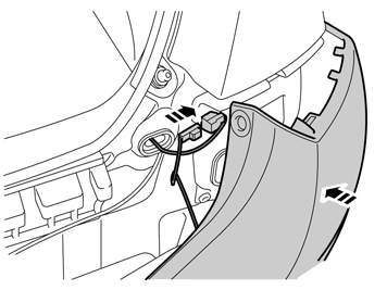
| | Raise the bumper cover to the car. Connect the connectors for parking assistance and license plate lighting. Reinstall the bumper cover with its screws. Reinstall the stops for the tailgate.
|
|  | | IMG-254251 |
|
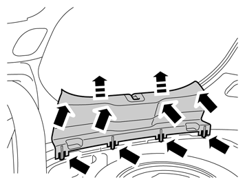
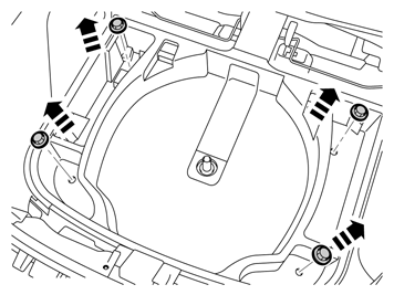
| | Reinstall in the cargo compartment: side panel clips for the cargo floor support sill molding sill trim panel applicable spare wheel jack and other parts in the cargo floor support the floor hatch
|
|  | | IMG-333974 |
|
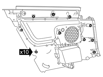
| | Note!
There are 10 clips on the reverse of the panel that must engage in the body. Take care when aligning so that the clips do not break. Broken clips must be replaced with new ones. |
|
|  | | IMG-251430 |
|
| | Reinstall the side panel by first aligning it on the sill at the front edge and then pressing it against the body side, ensure that all clips engage. Tighten the panel using existing screws.
|
|  | | IMG-251432 |
|
| | |
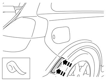
|  | | IMG-242268 |
|
| | |