| | Installing the front intake, applies to the S40/V50, -07 |
|  | | J8601099 |
|
| | Installing the front intake, applies to the S40/V50, -07 |
|  | | J8601100 |
|
| | |
|  | | J8601101 |
|
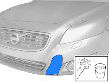
| | Remove the backing tape on the template from the kit. Press the template onto the embossing on the bumper cover. The marking (1) on the template must be opposite the front edge of the tape. The marking (2) on the template must be in line with the curve (3) at the top edge of the embossing on the bumper cover.
|
|  | | J8601102 |
|
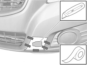
| | Take a sharp knife. First make a thin cut along the edges of the inside of the template. This provides a groove to follow. Then cut carefully out of the bumper cover.
Note!
Cut carefully. It is easy to slip with the knife and move outside the template. |
Remove the template. Install the protective cover for the front engine block heater socket from the kit. Check that it aligns. Adjust the hole using a knife or file as necessary. Smooth off the hole edges. Remove any swarf.
|
|  | | J8000359 |
|
| | |
|  | | J8601130 |
|
| | |
|  | | J8601131 |
|
| | |
|  | | J8601087 |
|
| | |
|  | | J8601084 |
|
|  | | J8903376 |
|
| | Illustration A Illustration B |
|  | | J8601086 |
|
| | Detach the ends of the bumper shell on the left and right-hand sides. Grasp the end of the bumper shell inside the fender liner. Carefully pull the end of the bumper shell so that the two catches on the inside release. Remove the bumper cover and air baffle. Pull the bumper cover and air baffle forwards until the remaining catches under the lamps release. Disconnect the connectors for the fog lamps if applicable.
|
|  | | J2900319 |
|
| | Press the protective cover (from the kit) into place in the hole cut in the bumper shell. Insert the cable for the front engine block heater socket together with the ground lead from the kit through the protective cover.
|
|  | | J2900320 |
|
|  | | J2900321 |
|
| | Illustration A Illustration B |
| | Installing the front intake, applies to the S40/V50, MY 07- |
| | | J8000359 |
|
| | Installing the front intake, applies to the S40/V50, MY 07- Remove the seven screws from the engine splash guard. |
| | | J8601130 |
|
| | |
|  | | IMG-265763 |
|
| | |
| | | J8601087 |
|
| | |
| | | J8601084 |
|
| | |
| | | J8903376 |
|
| | |
| | | J8601086 |
|
| | Detach the ends of the bumper cover on the left and right-hand sides. Grasp the end of the bumper cover inside the wing liner. Carefully pull the end of the bumper cover so that the two catches on the inside release. Remove the bumper cover and air baffle. Pull the bumper cover and air baffle forwards until the remaining catches under the lamps release. Disconnect the connectors for the fog lamps and parking assistance if applicable.
|
|  | | IMG-265777 |
|
| | Cut out the template by cutting along the outer edges of the dotted and solid line. place the template with the dotted section on the existing marking (periphery) on the bumper. Mark according to the new, slightly recessed marking. Cut off the upper dotted section of the template and finish the new marking all the way around.
|
|  | | IMG-265778 |
|
| | Using a sharp knife, first make a thin cut along the edges of the new marking inside of the bumper cover. Then carefully cut out the bumper cover hole.
Note!
Cut carefully. It is easy to slip with the knife and move outside the markings. |
Install the protective cover for the front engine block heater socket from the kit. Check that it aligns. Adjust the hole using a knife or file as necessary. Smooth off the hole edges. Remove any swarf.
|
|  | | IMG-265779 |
|
| | Take the protective cover from the kit and press it into the hole cut in the bumper cover. Take the cable for the front engine block heater socket with ground lead from the kit and thread them through the protective cover.
|
|  | | IMG-265781 |
|
| | |
|  | | IMG-265782 |
|
| | |
| | Installing the front intake (C70) |
|  | | IMG-225653 |
|
| | Installing the front intake (C70) |
|  | | IMG-225652 |
|
| | |
| | | J8903376 |
|
| | |
|  | | IMG-225651 |
|
| | |
|  | | IMG-227800 |
|
| | |
| | | J8601130 |
|
| | |
|  | | IMG-225649 |
|
| | Detach the right and left-hand ends of the bumper. Grip the bumper from the inside and pull it forward in order to detach the two holders under the headlamps. Remove the bumper, unplug the connectors for the fog lamps and place the bumper on a surface that does not damage the paintwork.
Hint
Removal of the bumper is facilitated if carried out by two people. |
|
|  | | IMG-225647 |
|
| | |
|  | | IMG-225646 |
|
| | |
|  | | IMG-225645 |
|
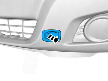
| | Locate the pre-marking on the inside of the bumper cover on the left-hand side of the car. Use a Ø 10mm (3/8") drill bit to drill inside the four corners of the marking area. Take a sharp knife and carefully cut out the pre-marked area in the bumper cover on the left-hand side of the car.
Note!
Cut carefully. It is easy to slip with the knife and move outside the markings. |
|
|  | | IMG-225644 |
|
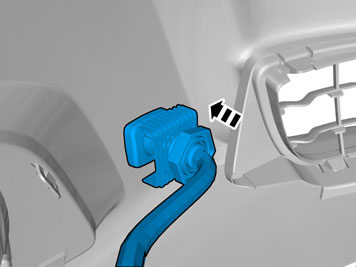
| | Remove swarf and smaller irregularities with a file. Do not damage the paintwork and follow the pre-marking accurately. Install the box for the front engine block heater socket from the kit. Check that it aligns. Adjust the hole using a knife or file as necessary. File down the edges of the holes.
|
|  | | IMG-225643 |
|
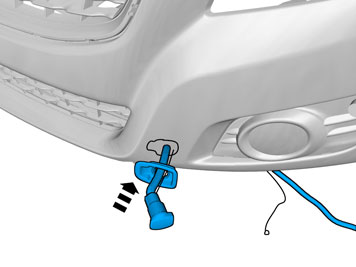
| | Take the cable harness with front socket and box from the kit. Route the cable through the box and fit the connector. Pull in the cable and align the box in the hole made in the bumper.
|
|  | | IMG-225642 |
|
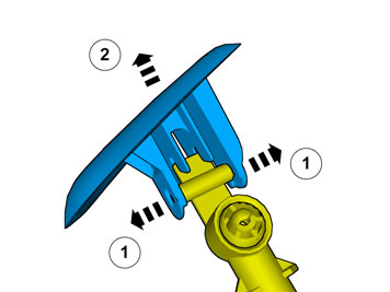
| | Take the bracket and the large plastic nut from the kit and thread the cable harness through them. Pull forward the bracket to the inside of the bumper and tighten the box with the large plastic nut. Plug the electrical connector into the front socket as a counterhold for when the latter is tightened.
|
|  | | IMG-225641 |
|
| | |
| | Installing the front intake (C70) 2010- |
|  | | IMG-332924 |
|
| | Installing the front intake (C70) 2010- |
|  | | IMG-332914 |
|
| | |
|  | | IMG-332916 |
|
| | Position the templates following the curves of the surface between the lower grille and panel for the fog lamps and tape it according to the image. Take a sharp knife. First make a thin cut along the edges of the inside of the template. This provides a groove to follow. Then cut carefully out of the bumper cover.
Note!
Cut carefully. It is easy to slip with the knife and move outside the template. |
Remove the template. Install the protective cover for the front engine block heater socket from the kit. Check that it aligns. Adjust the hole using a knife or file as necessary. Smooth off the hole edges. Remove any swarf.
|
| | | J8601130 |
|
| | |
| | | J8601131 |
|
| | |
| | | IMG-225652 |
|
| | |
|  | | IMG-332933 |
|
| | |
| | | IMG-227800 |
|
| | |
| | | IMG-225649 |
|
| | Detach the right and left-hand ends of the bumper. Grip the bumper from the inside and pull it forward in order to detach the two holders under the headlamps. Remove the bumper, unplug the connectors for the fog lamps and place the bumper on a surface that does not damage the paintwork.
Hint
Removal of the bumper is facilitated if carried out by two people. |
|
|  | | IMG-332938 |
|
| | Press the protective cover (from the kit) into place in the hole cut in the bumper shell. Insert the cable for the front engine block heater socket together with the ground lead from the kit through the protective cover.
|
|  | | IMG-332939 |
|
|  | | IMG-332943 |
|
| | |
| | | IMG-225646 |
|
| | |
|  | | IMG-247823 |
|
| | Installing the front intake, applies to the C30 |
|  | | IMG-248765 |
|
| | |
|  | | IMG-249205 |
|
|  | | IMG-247824 |
|
| | Illustration A Illustration B |
|  | | IMG-247825 |
|
| | Take a sharp knife. First make a thin cut along the edges of the inside of the template. This provides a groove to follow. Then cut carefully out of the bumper cover.
Note!
Cut carefully. It is easy to slip with the knife and move outside the template. |
Remove the template. Install the protective cover for the front engine block heater socket from the kit. Check that it aligns. Adjust the hole using a knife or file as necessary. Smooth off the hole edges. Remove any swarf.
|
| | | J8000359 |
|
| | |
|  | | IMG-247826 |
|
| | |
| | | J8601131 |
|
| | |
| | | J8601087 |
|
| | |
| | | J8601084 |
|
| | | J8903376 |
|
| | Illustration A Illustration B |
|  | | IMG-248768 |
|
|  | | IMG-247843 |
|
| | Illustration A Illustration B Remove the bumper cover with air baffle by grasping the ends and pulling forwards until the remaining hooks under the lamps release.
Note!
Get help from a colleague for this procedure. |
Disconnect the connectors for the fog lamps or parking assistance if applicable. Remove the pieces of tape from the edges of the wing.
|
|  | | IMG-247844 |
|
| | Press the protective cover (from the kit) into place in the hole cut in the bumper shell. Insert the cable for the front engine block heater socket together with the ground lead from the kit through the protective cover.
|
|  | | IMG-247845 |
|
|  | | IMG-247846 |
|
| | Illustration A Illustration B |
|  | | IMG-332918 |
|
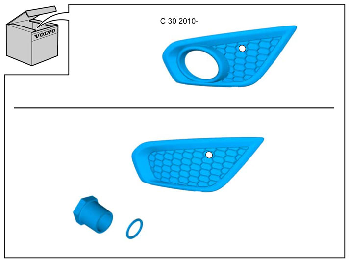
| | Installing the front intake, applies to the C30 2010- |
|  | | IMG-331946 |
|
| | |
|  | | IMG-331947 |
|
| | |
|  | | IMG-331948 |
|
| | |
|  | | IMG-332920 |
|
| | |
|  | | IMG-331989 |
|
|  | | IMG-331990 |
|
| | A Note!
The washer must be positioned as illustrated. |
B |
|  | | IMG-331991 |
|
| | |
|  | | IMG-225640 |
|
| | Applies to all car models where the bumper cover is removed Reinstall the bumper cover. Use the five clips and the two screws at the top edge. Ensure that the air baffle is correctly positioned in its mounting. Press in so that the clips under the headlamps fasten. Reconnect the connectors for the fog lamps and parking assistance if applicable.
Hint
Installation of the bumper is facilitated if carried out by two people. |
|
| | |
|  | | J2900313 |
|
| | |
|  | | IMG-360291 |
|
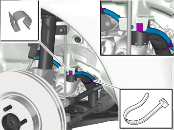
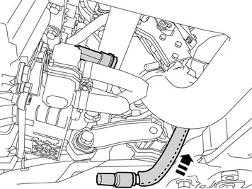
| | Route the front intake cable from the front edge of the washer fluid reservoir, along the bottom edge of the front member and over the drive shaft. Press the cable into the previously installed clips.
|
|  | | IMG-365113 |
|
| | |
|  | | J2900297 |
|
| | |
|  | | J2900298 |
|
| | Drill a Ø4 mm (5/32 ”) hole for the ground lead, on the outside of the left-hand front member, approximately as illustrated. Treat the edges of the holes using a rust-proofing agent.
|
|  | | J2900299 |
|
| | |
|  | | IMG-232644 |
|
| | |
|  | | IMG-232645 |
|
|  | | J2900316 |
|
| | Illustration A Illustration B |
|  | | D3601932 |
|
| | |
|  | | J2900302 |
|
| | Applies to cars where the engine block heater and passenger compartment connector socket are installed at the same time Take the bracket and the rubber guard from the kit for the passenger compartment connector socket. Press the rubber guard on to the bracket.
|
|  | | J2900296 |
|
| | Applies to cars where the engine block heater and passenger compartment connector socket are installed at the same time Tighten the junction connector at the bracket (included in the kit for the passenger compartment connector socket) in the position illustrated. Use the screw, toothed washer and nut from the kit. The bracket must be parallel to the length of the junction connector. Position (1) cable for the engine block heater Position (2) cable for the passenger compartment socket Position (3) cable from the front engine block heater socket.
|
|  | | J2900303 |
|
| | Applies to cars where the engine block heater and timer relay are installed at the same time Tighten the timer relay at the bracket (purchased separately) in the position illustrated. Use the screw, toothed washer and nut from the kit. The bracket must be parallel to the length of the timer relay. Connect the connector on the long cable harness (from the kit) to the timer relay. Press the rubber plug (1), part no. 346509, (purchased separately) into place on the free socket in the timer relay. Use butyl tape to secure the rubber plug. Position (2) cable for the engine block heater Position (3) cable from the front engine block heater socket.
|
|  | | J2900304 |
|
| | Applies to cars where the passenger compartment connector socket and the timer relay are installed at the same time Tighten the timer relay at the bracket (purchased separately) in the position illustrated. Use the screw, toothed washer and nut from the kit. The bracket must be parallel to the length of the timer relay. Connect the connector on the long cable harness (from the kit) to the timer relay. Position (1) cable for the passenger compartment socket Position (2) cable for the engine block heater Position (3) cable from the front engine block heater socket.
|
|  | | J2900292 |
|
| | Connect the short cable from the kit to the engine block heater, to the routed cable (1) from the front socket. (When fitting junction connector/timer relay at the same time, the cable from the front socket is connected to the single outlet on the junction connector/timer relay instead. Refer to the installation instructions for passenger compartment socket/timer relay). Firmly press the cable junction together.
|
|  | | J2900293 |
|
| | |
|  | | J2900294 |
|
| | |
| | Installing the engine block heater |
|  | | J2900295 |
|
| | Installing the engine block heater |
|  | | IMG-232646 |
|
| | |
|  | | IMG-214121 |
|
| | |
|  | | IMG-214122 |
|
| | |
|  | | IMG-214124 |
|
| | |
|  | | IMG-234800 |
|
| | Applies to cars with diesel engine Cut the remaining hose 15 mm (19/32") in the long, straight end.
|
|  | | IMG-214123 |
|
| | |
|  | | IMG-235624 |
|
| | |
|  | | IMG-235626 |
|
| | Connect the short electrical cable (which was routed earlier) to the engine block heater. Press it firmly into the engine block heater connection. Press in a locking sleeve from the kit over the cable splice.
|
|  | | IMG-235629 |
|
| | |
|  | | IMG-235630 |
|
|  | | IMG-236480 |
|
|  | | IMG-365515 |
|
| | Illustration A applies to the diesel engine Illustration B applies to petrol engines without turbo On cars with petrol engine without turbo, route the cable with radiation shield below the power steering hoses/pipes. Illustration C applies to petrol engine with turbo On cars with petrol engine and turbo, route the cable with radiation shield under the power steering hoses/pipes and under the turbo pipe. |
| | Reinstall the left-hand fender liner. Tighten the fender liner to the left-hand side member. Tighten the two wing liners to the bumper cover on the right and left-hand sides. Fill with coolant, run the engine to operating temperature, bleed the cooling system and check that there are no leaks. Reinstall the engine splash guard. Reinstall the front wheels and torque tighten the wheel nuts: Step 1: Wheel to wheel hub, 20 Nm Step 2: Wheel to wheel hub, 110 Nm
|