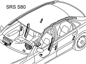
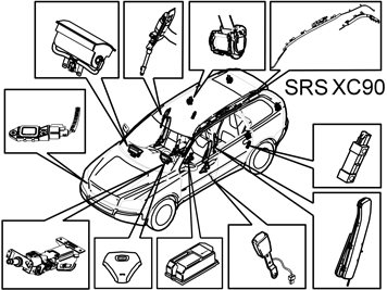
| | Steps 1–32 apply to the S60/S80 |
|  | | M8503480 |
|
| | Steps 1–32 apply to the S60/S80 |
|  | | M8503481 |
|
| | |
|  | | M8503482 |
|
| | |
|  | | M8503478 |
|
| | |
|  | | M8503479 |
|
| | |
|  | | IMG-258823 |
|
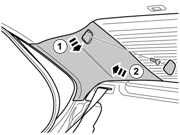
| | Applies to the S60 Remove the weatherstrip by the C pillar panel at the rear edge of the rear door opening. Remove cover and screw from the top of the panel. Pull the top edge of the C pillar panel inwards into the car (1). Fold the panel forwards (2) and lift it out.
|
|  | | IMG-258824 |
|
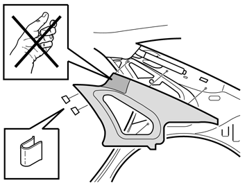
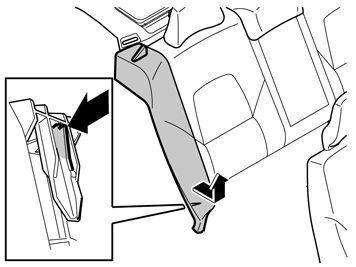
| | Applies to the S80 Remove the weatherstrip by the C pillar panel at the rear edge of the rear door opening. Remove the two steel clips at the front edge/upper edge of the panel. Pull the top edge of the C pillar panel inwards into the car. Fold the panel forwards and lift it out.
Note!
When removing the C pillar panel, do not grip it with your hand or with a tool in the area around the IC hatch (1), as the joint function in the hatch would then become deformed and it cannot be reset. |
|
|  | | IMG-258825 |
|
| | |
|  | | IMG-258826 |
|
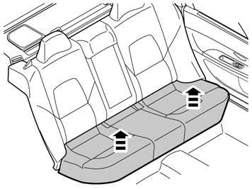
| | Applies to the S80 First lift the bottom edge of the short end of the cushion and then the front edge and pull it off.
Note!
The cushion may be securely attached. |
Lift out the cushion. Check that all the clips are intact. If not, they must be replaced.
|
| | |
|  | | M3702528 |
|
| | |
|  | | M3702529 |
|
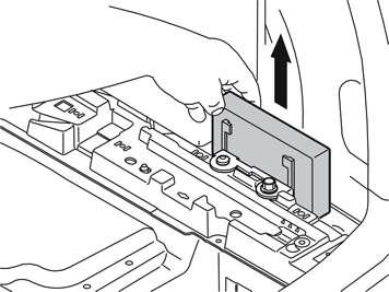
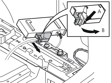
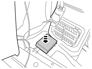
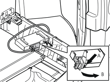
| | Disconnect the large connector from the accessory electronic module (AEM) by pressing in the catch (A) and pulling the black handle (B) in the direction of the arrows until a click is heard. Disconnect the connector from the accessory electronic module (AEM).
|
|  | | M3702530 |
|
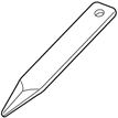
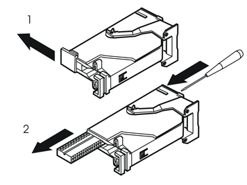
| | Remove: the black catch (1) holding the black switch in place in the connector by pulling in the direction of the arrow. the black switch (2) by inserting a pointed object in the hole in the other end. Press out.
|
|  | | M3702955 |
|
| | |
|  | | M3702956 |
|
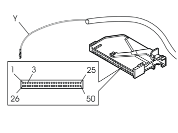
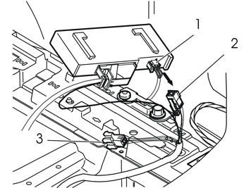
| | Remove the connector (1) from the accessory electronic module (AEM). Connect the corresponding connector (2) to the T-cable for the thick cable harness, for the accessory electronic module (AEM). Connect the remaining connector (3) on the T-cable to the connector that was disconnected from the accessory electronic module (AEM). Reinstall the accessory electronic module (AEM) in its bracket.
|
|  | | IMG-258827 |
|
| | |
|  | | IMG-258828 |
|
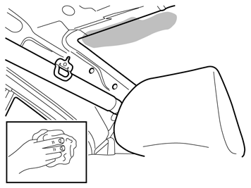
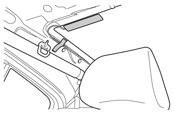
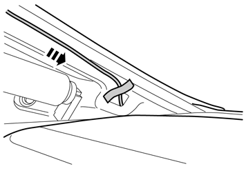
| | Press the antenna onto the inside of the window, as close to the panel edge as possible. Tape the cable securely in place.
|
|  | | IMG-258829 |
|
| | |
|  | | IMG-258831 |
|
| | |
|  | | M8703702 |
|
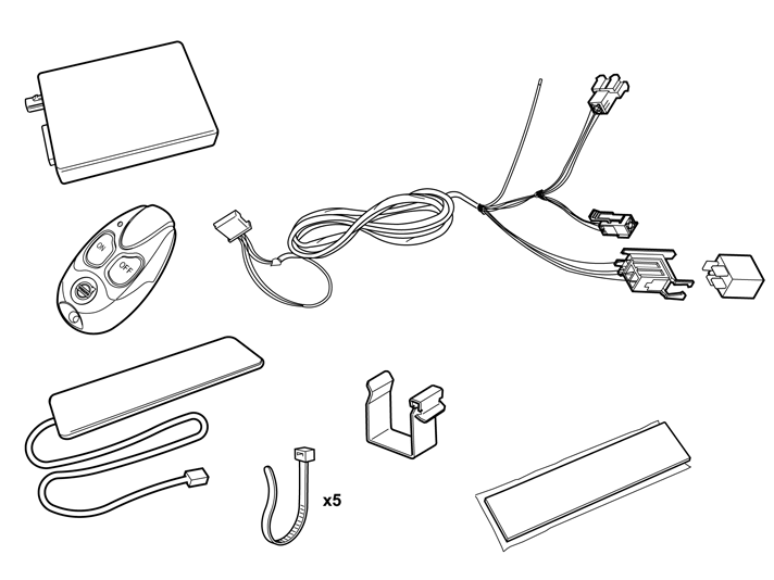
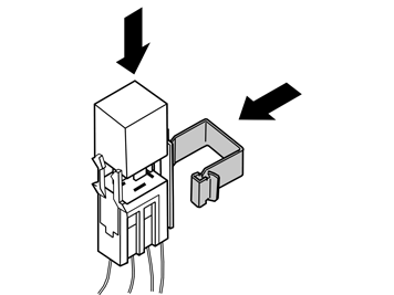
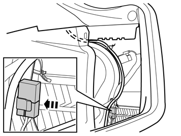
| | Take the relay and the large clip from the kit. Press the relay into the relay holder. Press the clip into the relay holder.
|
|  | | IMG-258832 |
|
| | |
|  | | IMG-222282 |
|
| | |
|  | | IMG-222283 |
|
| | |
|  | | IMG-222284 |
|
| | |
|  | | IMG-222286 |
|
| | |
|  | | IMG-225262 |
|
| | |
|  | | IMG-258843 |
|
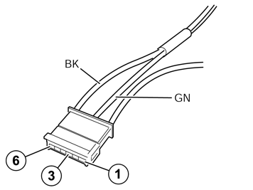
| | Connect the green (GN) cable from the kit to terminal 3, and the black (BK) cable to terminal 6 in the six pin connector. Press the secondary catch into place on the black six pin connector.
|
|  | | IMG-258663 |
|
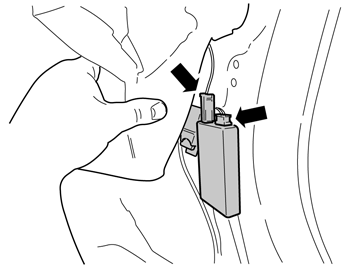
| | Synchronizing the Transmitter - Receiver Connect the negative battery cable in the car. Connect the aerial cable to the receiver unit. Connect the connector to the receiver unit. Within the time interval 1.5 to 5 seconds, press the "OFF" button on the transmitter until the LED goes out.
Synchronisation complete. Note!
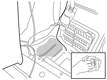
Tape up any cable excess from the timer relay and place next to the control module under the insulation. |
|
|  | | IMG-258846 |
|
| | |
|  | | IMG-222287 |
|
| | |
|  | | IMG-258864 |
|
| | |
| | |
|  | | IMG-242268 |
|
| | |
| | Steps 33–54 apply to the V70 |
|  | | M8502718 |
|
| | Steps 33–54 apply to the V70 |
|  | | M8503069 |
|
| | |
|  | | M8503008 |
|
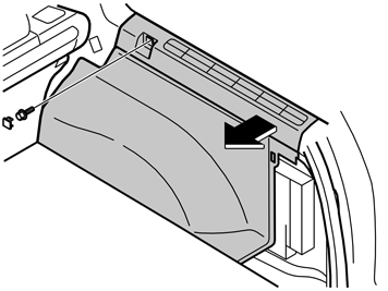
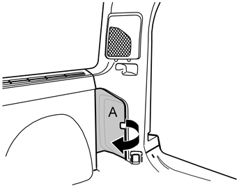
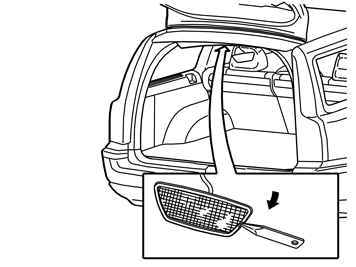
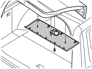
| | Remove the right side panel by first removing the cover and the screw in the front edge. Pull the top of the panel out until the clips release. Fold the panel inwards. Lift the panel out.
|
|  | | M8504252 |
|
| | |
|  | | M8504269 |
|
| | |
|  | | M8504271 |
|
| | |
|  | | M8503005 |
|
| | |
|  | | M8503010 |
|
| | Caution!
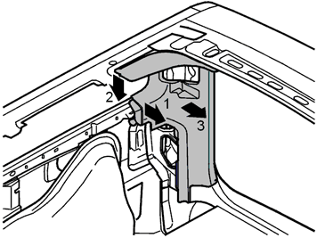
Remove the panel in the following order otherwise the panel may become damaged. |
1 - Grip the edge and pull inward so that the clips release. 2 - Detach the upper edge at the window so that the panel can pass the gas strut. 3 - Pull inward to make the clips in the opening release. 4 - Lift the panel upwards.
|
|  | | M3702528 |
|
| | |
|  | | M3702530 |
|
| | Remove: the black catch (1) holding the black switch in place in the connector by pulling in the direction of the arrow. the black switch (2) by inserting a pointed object in the hole in the other end. Press out.
|
|  | | M3702955 |
|
| | |
|  | | M3702956 |
|
| | Remove the connector (1) from the accessory electronic module (AEM). Connect the corresponding connector (2) to the T-cable for the thick cable harness, for the accessory electronic module (AEM). Connect the remaining connector (3) on the T-cable to the connector that was disconnected from the accessory electronic module (AEM). Reinstall the accessory electronic module (AEM) in its bracket.
|
|  | | IMG-259205 |
|
| | |
|  | | IMG-259206 |
|
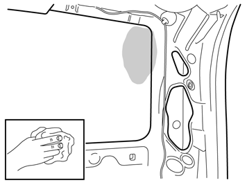
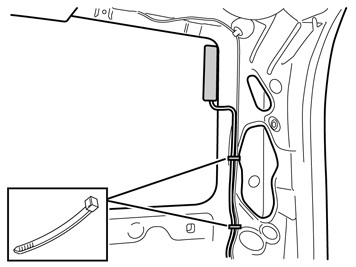
| | Press the antenna onto the inside of the window, as close to the panel edge as possible. Clamp the cable at the existing cable harness.
|
|  | | M8703709 |
|
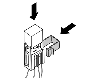
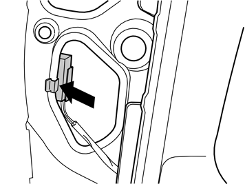
| | Take the relay and the large clip from the kit. Press the relay into the relay holder. Press the clip into the relay holder.
|
|  | | M8703710 |
|
| | |
| | |
|  | | IMG-259643 |
|
| | |
|  | | IMG-222287 |
|
| | |
|  | | IMG-259227 |
|
| | |
| | |
|  | | IMG-242268 |
|
| | |
| | Steps 55 - 62 apply to XC90 |
|  | | R8902691 |
|
| | Steps 55 - 62 apply to XC90 |
|  | | R8902931 |
|
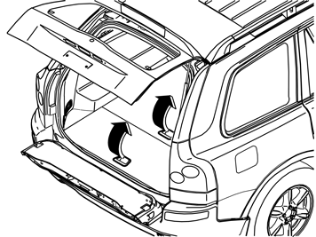
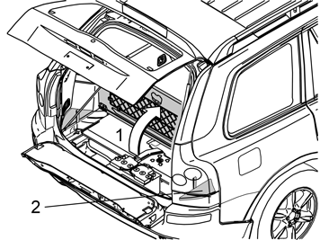
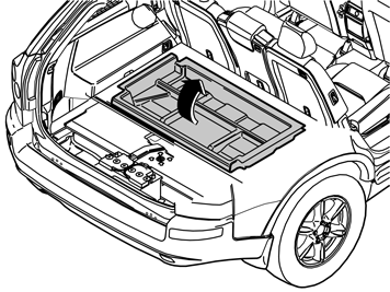
| | Applies to cars with three rows of seats and integrated carrier bag holder on the underside of the centre floor hatch Fold up the centre rear floor hatch (1). Detach the two straps on the underlying panel. Lift up the rear edge of the panel, fold the floor hatch back and lift out the floor hatch with the panel.
Applies to cars with three rows of seats without an integrated carrier bag holder Lift up the centre rear floor hatch at the rear edge and lift it out.
|
|  | | R8504293 |
|
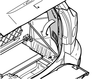
| | Applies to cars with two rows of seats Remove the front storage box.
|
|  | | R8504159 |
|
| | |
|  | | R8504086 |
|
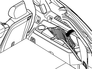
| | Carefully pull off the top edge of the right-hand D pillar panel. Continue down until the three clips have released. Remove the panel by pulling it straight up and unhook it from the side panel. If applicable, disconnect the connector for the D pillar loudspeaker.
|
|  | | R3702881 |
|
| | |
|  | | R3702909 |
|
| | |
| | |

