| | |
|  | | IMG-265203 |
|
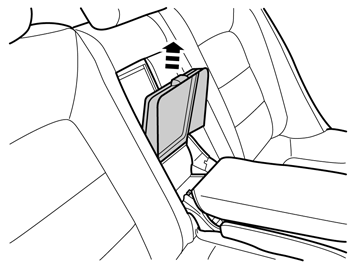
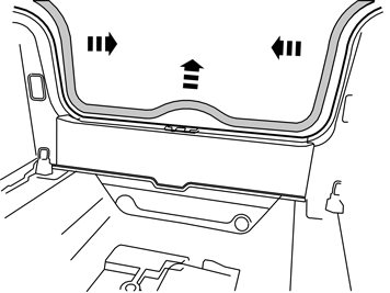
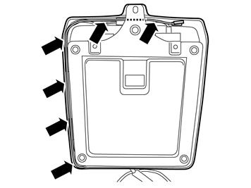
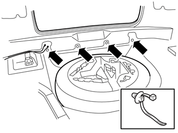
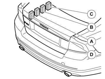
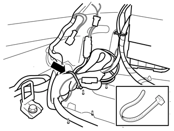
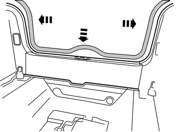
| | Preparations Applies to all models |
|  | | IMG-226720 |
|
| | |
|  | | IMG-265204 |
|
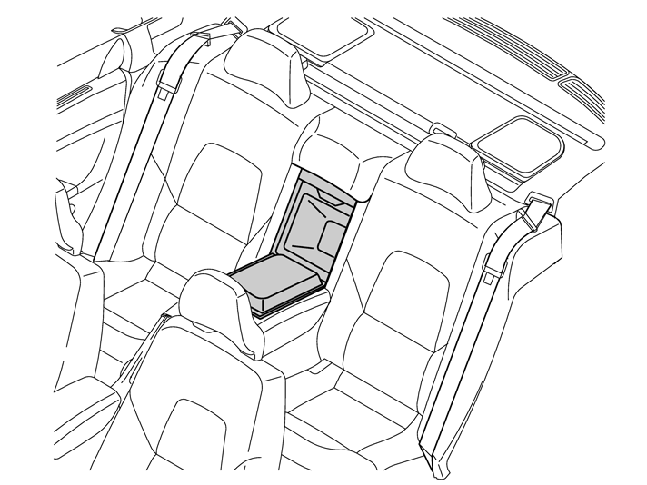
| | Applies to cars with integrated child seat in the middle of the backseat |
|  | | IMG-307066 |
|
| | Applies to cars without integrated child seat in the middle of the backseat |
|  | | IMG-307083 |
|
| | |
|  | | IMG-307084 |
|
|  | | IMG-307085 |
|
| | |
|  | | IMG-307086 |
|
| | |
|  | | IMG-307087 |
|
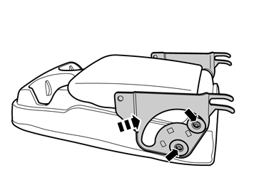
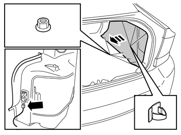
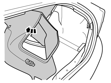
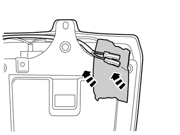
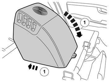
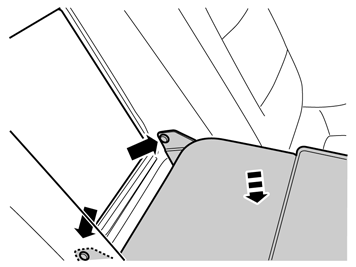
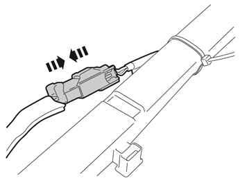
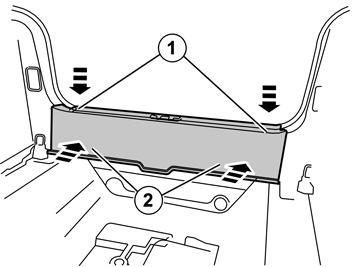
| | Applies to all models Fold the backrest forward. Remove the seat belt from the guide on the left side cushion. Insert a hand from the side of the upper section of the side bolster. Press in the catches properly and jerk the upper edge of the bolster so that the two catches on the other side release. Lift the bolster from the mounting at the lower edge.
|
|  | | IMG-307088 |
|
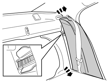
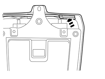
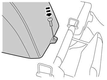
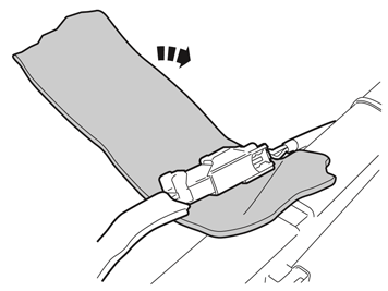
| | Remove the screw in the opener for the cover for long load, swing out the opener and remove it. The screw shall be used again, but not the opener.
|
|  | | IMG-226722 |
|
| | |
|  | | IMG-226721 |
|
| | |
|  | | IMG-265207 |
|
|  | | IMG-307089 |
|
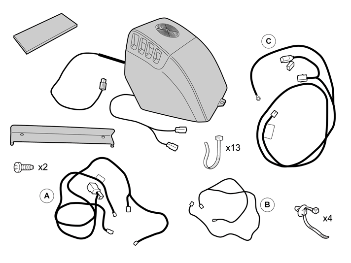
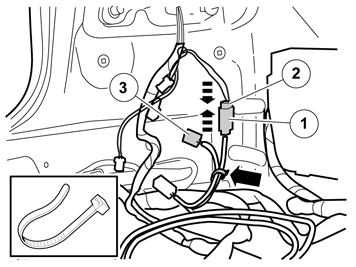
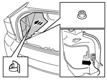
| | A Remove: cover in right-hand side panel. the three clips in the top edge of the side panel. the three rear plastic nuts at the rear edge of the side panel. the connector to the cargo compartment lighting.
B |
|  | | IMG-265640 |
|
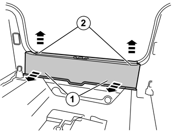
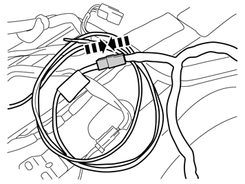
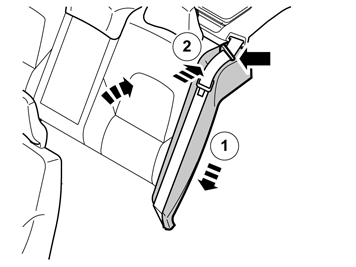
| | Remove: the cover in left-hand side panel. the three clips in the top edge of the side panel. the three rear plastic nuts at the rear edge of the side panel. the connector to the cargo compartment lighting. Lift out the side panel.
|
|  | | IMG-301443 |
|
|  | | IMG-301444 |
|
| | |
|  | | IMG-308143 |
|
| | |
|  | | IMG-301446 |
|
|  | | IMG-308144 |
|
| | |
| | |
|  | | IMG-308243 |
|
|  | | IMG-308244 |
|
| | Installation Applies to all models A and B Note!
Make sure that the hidden lead end is not trapped when the cooler is installed. |
|
|  | | IMG-308245 |
|
| | |
|  | | IMG-308270 |
|
| | |
|  | | IMG-265210 |
|
| | |
|  | | IMG-308284 |
|
| | Applies to cars without integrated child seat in the middle of the backseat |
|  | | IMG-308285 |
|
| | |
|  | | IMG-308303 |
|
|  | | IMG-308347 |
|
| | A and B Route the cable harness from the cooler back in the luggage compartment along the cable conduit's left side. Clamp down the cable harness to the cable conduit with strip clamps. Do not tighten the clamps yet. Move the backrest with the cooler back and forth, and check the cable harness' movement. Tighten down the strip clamps with the cable harness in best position so that it does not contact with the bracket for the backrest.
|
|  | | IMG-308348 |
|
| | |
| | | IMG-308143 |
|
| | |
|  | | IMG-308349 |
|
| | |
|  | | IMG-308362 |
|
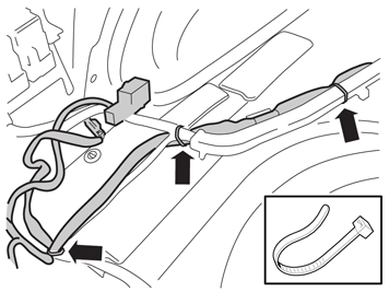
| | Continue to route the cable harness back along the cable conduit and existing cable harness. The leads with grey connector and relay with relay holder are located as shown. Later, the rest of the cable harness shall be routed along the rear trunk over to the right side, if the car is provided with pre-wired connector to 12V socket. Clamp the cable harness with strip clamps.
|
|  | | IMG-308363 |
|
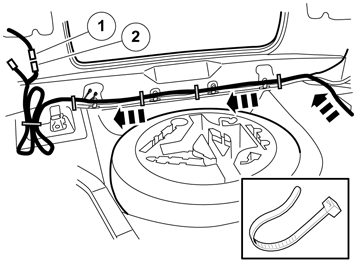
| | Applies to cars with pre-wired connector for 12V socket and that has cable harness routed along the rear trunk Route the longer part of the cable harness A behind the cargo lashing eye along existing cable harness on the rear trunk to the luggage compartment's right side. Clamp in the cable harness to the existing cable harness using cable ties.
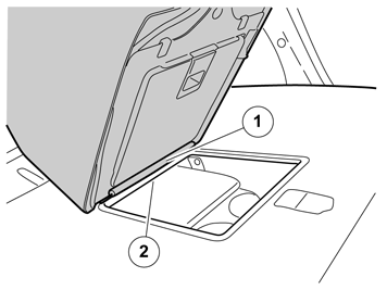
Applies to cars with a 12V socket Plug in the two-pin male connector (1) which was disconnected from the 12V socket to corresponding connection (2) in the routed cable harness. The remaining connection in the routed cable harness is later connected to the 12V socket when the side panel is reinstalled. Clamp up the extra lead with strip clamp.
Applies to cars without 12V socket |
|  | | IMG-308364 |
|
| | Applies to cars with pre-wired connector for 12V socket, but does not have cable harness along the rear trunk Note!
Install the clamps so that the strip clamp is inserted from below. |
|
|  | | IMG-308365 |
|
| | Applies to cars with a 12V socket Plug in the two-pin male connector (1) which was disconnected from the 12V socket to corresponding connection (2) in the routed cable harness. Later the remaining connection in the routed cable harness is connected to the 12V socket when the side panel is reinstalled. Clamp up the extra lead with a strip clamp.
Applies to cars without 12V socket |
|  | | IMG-308383 |
|
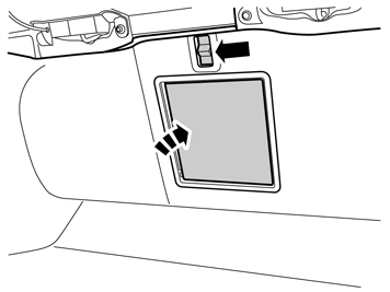
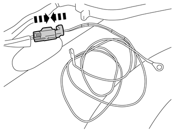
| | Applies to cars without pre-wired connector for 12V socket Get cable harness C from the kit and plug in the grey two-pin connector (1) to the pre-wired grey connector (2) under the left tail light. Left-over grey connector (3) is clamped. If the car is equipped with TRM and/or ECU, the two-pin connector is connected to one of these. Unplug the connector from any of them and connect the cable harness' grey connector between TRM/ECU and the unplugged connector.
|
|  | | IMG-308384 |
|
| | |
|  | | IMG-308385 |
|
| | Applies to all models Connecting power supply and ground for cable harness B |
|  | | IMG-308386 |
|
|  | | IMG-308387 |
|
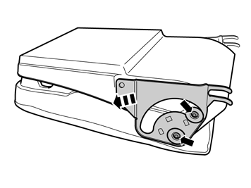
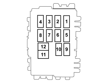
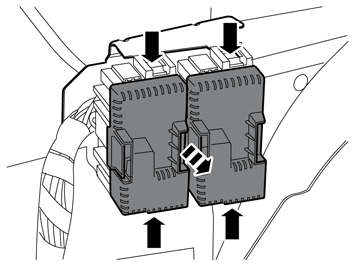
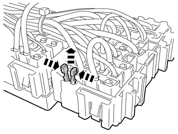
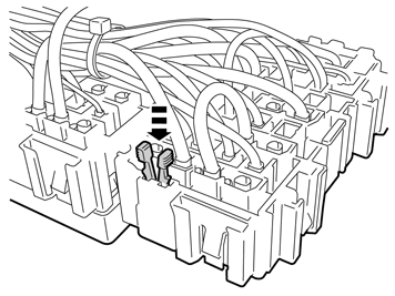
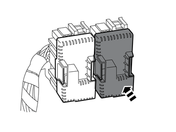
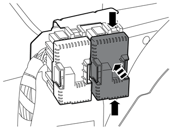
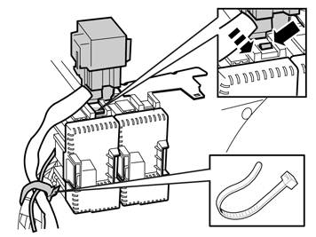
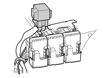
| | A and B Placement of relay/fuse modules (RJB A-D) with fuse/relay positions. The number of modules varies depending on car model, but the mutual placement is always the same. Car with two modules shown when connecting. |
|  | | IMG-308388 |
|
| | |
|  | | IMG-308389 |
|
| | |
|  | | IMG-286143 |
|
| | |
|  | | IMG-286144 |
|
|  | | IMG-308392 |
|
| | |
|  | | IMG-308393 |
|
| | |
|  | | IMG-308394 |
|
| | |
|  | | IMG-308395 |
|
| | Applies to cars with two fuse/relay modules Applies to cars with three or four fuse/relay modules |
|  | | IMG-308396 |
|
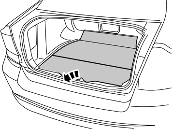
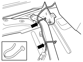
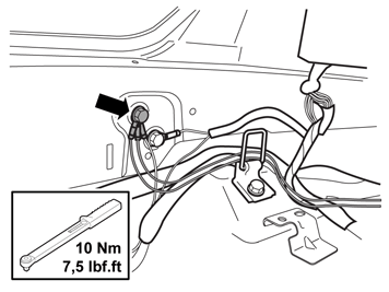
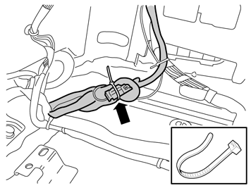
| | Applies to cars with pre-wired connector for 12V socket Loosen the upper ground screw on the left side in the rear trunk. If the car is equipped with trailer hitch, a ground cable is already installed. Connect the ground cable from cable harness B and tighten the screw with 10 Nm (7.5 lbf ft). Place the ground cable behind the cargo lashing eye.
|
|  | | IMG-308397 |
|
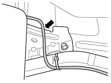
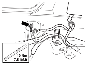
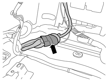
| | Applies to cars without pre-wired connector for 12V socket Loosen the upper ground screw on the left side in the rear trunk. If the car is equipped with trailer hitch, a ground cable is already installed. Connect the ground cables from the cable harnesses B and C and tighten down the screw with 10 Nm (7.5 lbf ft.). Place the ground cables behind the cargo lashing eye.
|
|  | | IMG-308398 |
|
|  | | IMG-308399 |
|
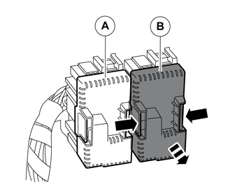
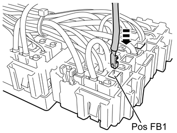
| | A Get the relay holder with bracket and relay in cable harness A and pres into the bracket in the rear module. Clamp the cable to the relay and the cable that was connected on the back of the module RJB B with strip clamp to the thick cable harness to the modules.
B The figure shows relay placement on car with three modules. Same placement of relay with bracket also on cars with four modules. |
|  | | IMG-308400 |
|
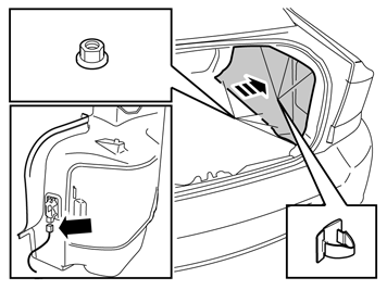
| | Applies to cars with pre-wired connector for 12V socket If the car is equipped with electric parking brake or media player, make sure that cable harnesses are clamped together and routed so that they do not chafe against the brackets for these. |
| | | IMG-308143 |
|
| | |
|  | | IMG-308404 |
|
| | |
|  | | IMG-308406 |
|
| | Applies to cars without pre-wired connector for 12V socket If the car is equipped with electric parking brake or media player, make sure that cable harnesses are clamped together and routed so that they do not chafe against these brackets. Bundle the excess cable from cable harnesses A, B, and C with connectors and the small fuse holder, and clamp with a strip clamp. Clamp excess cable around the connectors and fuse holder so that they do not rattle.
|
| | |
|  | | IMG-265225 |
|
| | |
|  | | IMG-308407 |
|
| | |
|  | | IMG-308408 |
|
| | |
|  | | IMG-226735 |
|
| | |
|  | | IMG-226734 |
|
| | |
|  | | IMG-255793 |
|
| | |