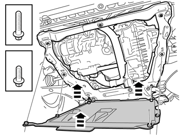
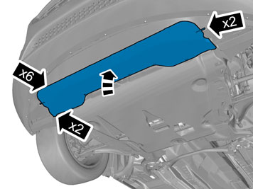
2016 L.H.D

Installation Instruction

Installation instructions, accessories
Volvo Car Corporation Gothenburg, Sweden
V60 2016
V60 (-18) 2016

Instruction NoVersionPart. No.Click to download PDF-version of this Installation Instruction
313165271.531370000, 31316732, 31316517
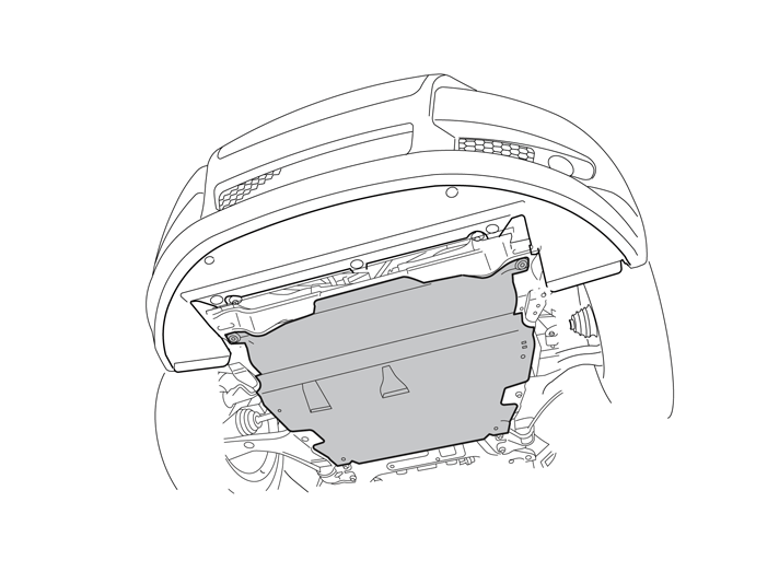
Protective plate, beneath the engine


IMG-304503


Equipment
A0000162
IMG-304663
IMG-239664
IMG-239660
IMG-304523

IMG-340412


INTRODUCTION

  • Read through all of the instructions before starting installation.

  • Notifications and warning texts are for your safety and to minimise the risk of something breaking during installation.

  • Ensure that all tools stated in the instructions are available before starting installation.

  • Certain steps in the instructions are only presented in the form of images. Explanatory text is also given for more complicated steps.

  • In the event of any problems with the instructions or the accessory, contact your local Volvo dealer.

 
1
IMG-340317
 

Applies to the S60(11-)

  • Remove air baffle.

2
IMG-231309
 

Applies to all models

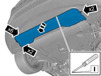
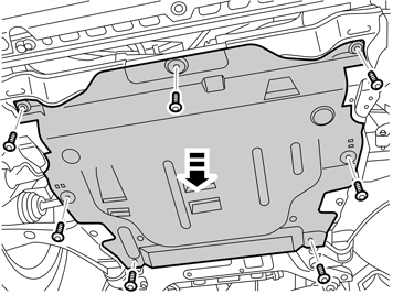
  • Remove the screws and the engine splash guard.

  • Place everything to one side. New material can be found in the kit.

3
IMG-304563
 

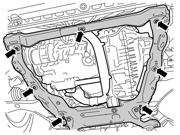
  • Remove the clips for the protective plate mounting in the subframe.

  • Place the clips to one side. New ones can be found in the kit.

4
IMG-304564
 

  • Cover the underneath of the engine with cardboard or similar, so that drilling swarf does not blow up into the engine compartment.

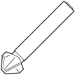
  • Carefully drill out the rectangular holes where the clips were located. Use tool P/N 9814112.

  • Remove any swarf.

5
IMG-304565
 

  • Take the rivet nuts from the kit and tighten in the drilled holes. Use tool P/N 9512782.

6
IMG-304583
 

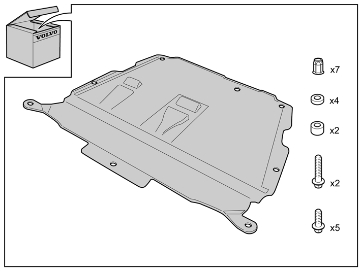
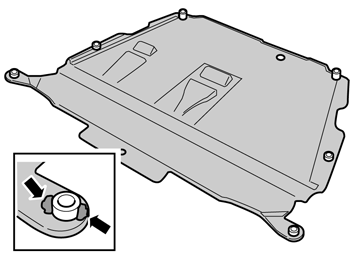
  • Take the new protective plate with screws and spacers from the kit.

  • Position the protective plate so that the high spacers with the longer screws are at the back, and the four low spacers with the shorter screws at the sides are at the front.

  • Secure the spacers on the protective plate opposite the holes using pieces of butyl tape.

7
IMG-340413


Note!

Get help from a colleague for this procedure.


  • Lift the protective plate into position.

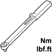
  • Install the screws. Position the long screws are the back. Tighten them to 30 Nm (22 lbf.ft.).

  • Slacken the screws two turns.

  • Tighten the screws. Tighten to 24 Nm (18 lbf. ft.).

8
IMG-340318
 

Applies to the S60(11-)