| | |
| | Read through all of the instructions before starting installation. Notifications and warning texts are for your safety and to minimise the risk of something breaking during installation. Ensure that all tools stated in the instructions are available before starting installation. Certain steps in the instructions are only presented in the form of images. Explanatory text is also given for more complicated steps. In the event of any problems with the instructions or the accessory, contact your local Volvo dealer.
|
| | |
| | Where the procedure differs, the right-hand version is also shown with text and image. |
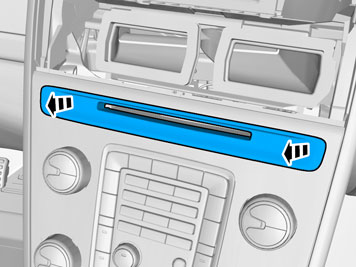
|  | | IMG-332193 |
|
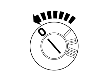
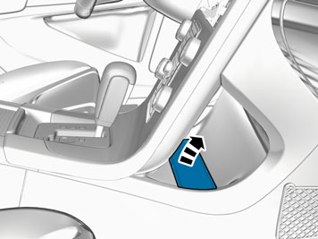
| | Set the ignition key to position 0. |
| | |
|  | | IMG-345728 |
|
| | |
|  | | IMG-345734 |
|
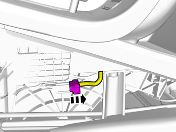
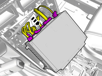
| | Disconnect the connector. |
|  | | IMG-345736 |
|
| | Note!
Perform the procedure one side at a time. |
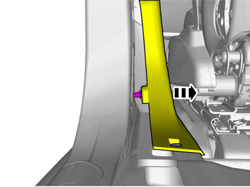
Release the catch. |
|  | | IMG-345737 |
|
| | |
|  | | IMG-345744 |
|
| | |
|  | | IMG-345745 |
|
| | |
|  | | IMG-340598 |
|
| | |
|  | | IMG-340599 |
|
| | Fold the carpet to the side. Unhook the clip(s). Disconnect the connector.
|
|  | | IMG-340600 |
|
| | |
| | Vehicles with the 4C system. |
|  | | IMG-340601 |
|
| | Disconnect the connector. |
| | Cars with automatic transmissions |
|  | | IMG-340596 |
|
| | |
|  | | IMG-293007 |
|
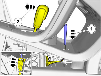
| | Release the shift-lock function. Move the gear lever to D.
|
| | Cars with manual transmissions |
|  | | IMG-345747 |
|
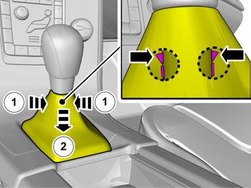
| | Release the lock ring which is located inside the gear lever boot. Pull the locking sleeve and gear lever boot down. Take care so that the boot does not come loose from the lock ring.
|
|  | | IMG-348272 |
|
| | |
| | |
|  | | IMG-340602 |
|
| | Note!
Protect adjacent components with tape. |
|
|  | | IMG-345753 |
|
| | |
|  | | IMG-293010 |
|
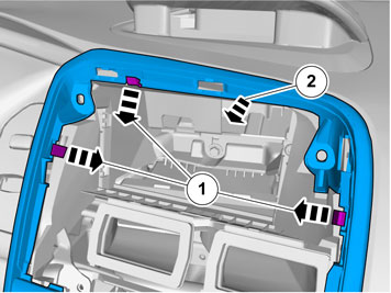
| | Release the catches. Detach the panel.
|
|  | | IMG-345754 |
|
| | |
|  | | IMG-340604 |
|
| | Disconnect the connector. |
|  | | IMG-345756 |
|
| | |
|  | | IMG-345762 |
|
| | |
|  | | IMG-345763 |
|
| | |
|  | | IMG-346936 |
|
| | |
|  | | IMG-345765 |
|
| | |
| | | IMG-345756 |
|
| | |
|  | | IMG-340622 |
|
| | |
|  | | IMG-345767 |
|
| | |
|  | | IMG-345766 |
|
| | |
|  | | IMG-345769 |
|
| | Note!
The number of connectors, cables and cable ties can vary depending on the vehicle's equipment level. |
Disconnect the connectors. |
|  | | IMG-341780 |
|
| | |
|  | | IMG-341781 |
|
| | |
|  | | IMG-341782 |
|
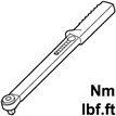
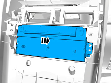
| | Remove the screws.
Tightening torque: M8
, 24 Nm
|
|  | | IMG-341773 |
|
| | |
|  | | IMG-341776 |
|
| | |
|  | | IMG-341777 |
|
| | Disconnect the connector. |
|  | | IMG-346026 |
|
| | Remove the screw.
Tightening torque: M8
, 24 Nm
|
|  | | IMG-341771 |
|
| | Fold the carpet to the side. Remove the screw.
Tightening torque: M8
, 24 Nm
|
|  | | IMG-341746 |
|
| | Fold the carpet to the side. Remove the screw.
Tightening torque: M8
, 24 Nm
|
|  | | IMG-345770 |
|
| | |
|  | | IMG-346281 |
|
| | |
|  | | IMG-345774 |
|
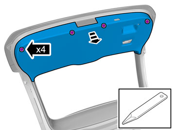
| | Note!
The screws are to be reused. |
Remove the screws. |
|  | | IMG-345773 |
|
| | |
| | Vehicles with 5 inch ICM-display |
|  | | IMG-348526 |
|
| | Note!
If the connection is missing the display must be replaced. |
|
| | Vehicles with 7 inch display |
|  | | IMG-352166 |
|
| | Disconnect the connector, if applicable. Attach the connector to the wiring harness. Use: , Wiring tape
|
| | |
|  | | IMG-345776 |
|
| | Note!
The number of connectors, cables and cable ties can vary depending on the vehicle's equipment level. |
Disconnect the connectors. |
|  | | IMG-346687 |
|
| | |
|  | | IMG-346689 |
|
| | |
|  | | IMG-346676 |
|
| | |
|  | | IMG-346681 |
|
| | |
|  | | IMG-346677 |
|
| | |
|  | | IMG-346682 |
|
| | |
|  | | IMG-341901 |
|
| | |
| | Vehicles with heated rear seat |
|  | | IMG-341902 |
|
| | Disconnect the connector. On both sides. |
| | |
|  | | IMG-346706 |
|
| | |
|  | | IMG-343672 |
|
| | |
|  | | IMG-347681 |
|
| | |
|  | | IMG-346792 |
|
| | |
|  | | IMG-347137 |
|
| | |
|  | | IMG-347136 |
|
| | |
|  | | IMG-346701 |
|
| | |
|  | | IMG-346797 |
|
| | |
|  | | IMG-346796 |
|
| | |
|  | | IMG-367311 |
|
| | |
|  | | IMG-367312 |
|
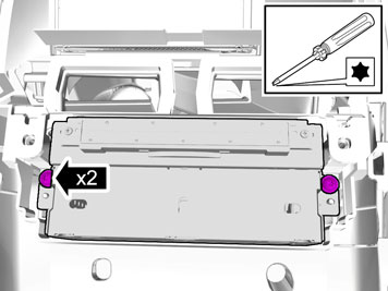
| | Remove the screws.
Tightening torque: Front seat to body
, 40 Nm
|
|  | | IMG-367314 |
|
| | |
|  | | IMG-367315 |
|
| | Remove the screws.
Tightening torque: Front seat to body
, 40 Nm
|
|  | | IMG-347391 |
|
| | |
|  | | IMG-346921 |
|
| | |
|  | | IMG-346811 |
|
| | |
|  | | IMG-343420 |
|
| | |
|  | | IMG-346862 |
|
| | |
|  | | IMG-346861 |
|
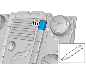
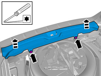
| | Remove the screws. Remove the panel.
|
|  | | IMG-347011 |
|
| | |
|  | | IMG-347026 |
|
| |
Use special tool: T9995919, PULLER (SEAL-PINION,CAM-CRANKSHAFT)B200-6304
|
|  | | IMG-347331 |
|
| | Remove the screws.
Tightening torque: M8
, 24 Nm
|
|  | | IMG-347040 |
|
| | |
|  | | IMG-347036 |
|
| | |
|  | | IMG-347051 |
|
| | |
|  | | IMG-346866 |
|
| | Remove the screw. Repeat on the other side. |
|  | | IMG-346872 |
|
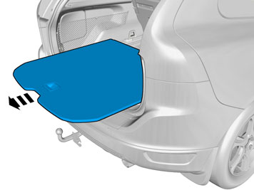
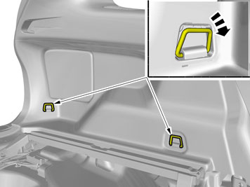
| | Detach the panel. Repeat on the other side. |
|  | | IMG-346876 |
|
| | Detach the panel. Repeat on the other side. |
|  | | IMG-346882 |
|
| | |
|  | | IMG-346886 |
|
| | |
|  | | IMG-346887 |
|
| | |
|  | | IMG-346891 |
|
| | |
|  | | IMG-346892 |
|
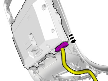
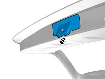
| | Disconnect the connector. |
| | Vehicles with power liftgate |
|  | | IMG-347056 |
|
| | |
|  | | IMG-347057 |
|
| | Disconnect the connector. |
| | |
|  | | IMG-346916 |
|
| | |
|  | | IMG-346917 |
|
| | |
|  | | IMG-346918 |
|
| | |
|  | | IMG-347071 |
|
| | |
|  | | IMG-347096 |
|
| | |
|  | | IMG-347097 |
|
| | Disconnect the connector. |
|  | | IMG-347106 |
|
| | |
|  | | IMG-347107 |
|
| | |
|  | | IMG-347117 |
|
| | |
|  | | IMG-348197 |
|
| | |
|  | | IMG-347142 |
|
| | |
|  | | IMG-348198 |
|
| | |
| | | IMG-347071 |
|
| | |
|  | | IMG-347206 |
|
| | |
|  | | IMG-348136 |
|
| | |
|  | | IMG-348137 |
|
| | |
|  | | IMG-348138 |
|
| | |
|  | | IMG-348146 |
|
| | |
|  | | IMG-347186 |
|
| | |
|  | | IMG-348156 |
|
| | |
|  | | IMG-347357 |
|
| |
Use special tool: T9512932, Tension spring
|
|  | | IMG-347256 |
|
| | |
|  | | IMG-347257 |
|
| | |
|  | | IMG-347258 |
|
| | |
|  | | IMG-347261 |
|
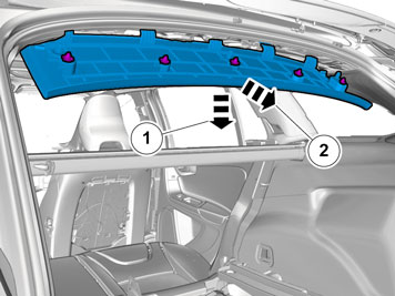
| | Fold the insulation to one side. Route the cable harness to the existing cable harness.
|
|  | | IMG-347262 |
|
| | |
|  | | IMG-347411 |
|
| | Fold the insulation to one side. |
|  | | IMG-347407 |
|
| | Route the cable harness to the existing cable harness. |
|  | | IMG-347409 |
|
| | |
|  | | IMG-347326 |
|
| | |
|  | | IMG-347327 |
|
| | |
|  | | IMG-347550 |
|
| | |
|  | | IMG-348230 |
|
| |
Use special tool: T9512932, Tension spring
|
|  | | IMG-348229 |
|
| | |
| | Vehicles with 5 inch ICM-display |
| | | IMG-348526 |
|
| | Note!
If the connection is missing the display must be replaced. |
|
|  | | IMG-348747 |
|
| | |
| | |
|  | | IMG-348748 |
|
| | Note!
The number of connectors, cables and cable ties can vary depending on the vehicle's equipment level. |
Connect the connectors. |
| | Vehicles with 5 inch ICM-display |
|  | | IMG-352266 |
|
| | |
| | Vehicles with 7 inch display |
|  | | IMG-352267 |
|
| | |
| | |
|  | | IMG-345864 |
|
| | |
| | | IMG-345774 |
|
| | |
|  | | IMG-345861 |
|
| | Note!
The number of connectors, cables and cable ties can vary depending on the vehicle's equipment level. |
Connect the connectors. |
|  | | IMG-345862 |
|
| | |
| | | IMG-345767 |
|
| | |
|  | | IMG-348206 |
|
| | |
|  | | IMG-348379 |
|
| | |
|  | | IMG-348323 |
|
| | Fold the carpet to the side. |
|  | | IMG-348322 |
|
| | Locate the existing connectors in the vehicle's cable harness. |
|  | | IMG-348324 |
|
| | Caution!
Make sure that no part of the wiring harness is trapped. |
Fold the floor carpet back. |
|  | | IMG-348216 |
|
| | |
|  | | IMG-348217 |
|
| | |
|  | | IMG-348218 |
|
| | |
|  | | IMG-348238 |
|
| | |
|  | | IMG-348223 |
|
| | |
|  | | IMG-367232 |
|
| | Check that the cable harness does not hang down and touch the newly installed control module. |
|  | | IMG-367234 |
|
| | Push up and secure the cable harness as necessary. |
| | Reinstall the removed parts in reverse order. |
|  | | IMG-332195 |
|
| | Set the ignition key to position II. |
|  | | IMG-242268 |
|
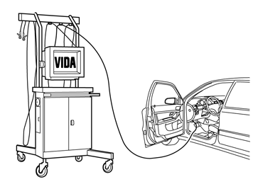
| | Download software (application) for the accessory's function according to the service information in VIDA. See VIDA or the accessories catalogue for software part number. |
| | Calibrate according to: DIAGNOSTICS/VEHICLE COMMUNICATION/Advanced/PAC/Service calibration, parking camera |