| | |
| 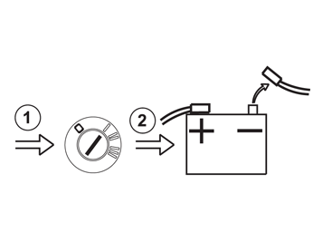 | | IMG-237320 |
|
| | Note!
The SRS system remains active for a brief period after power is cut off. Thus, wait three minutes before starting work. |
|
|  | | IMG-329033 |
|
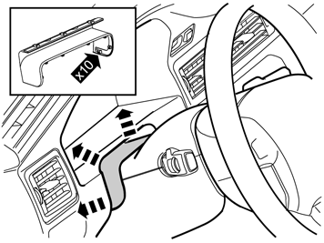
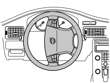
| | Loosen the lever and pull the steering wheel console backwards. Carefully prize off the rubber seal in the steering wheel cover all around. |
|  | | IMG-329034 |
|
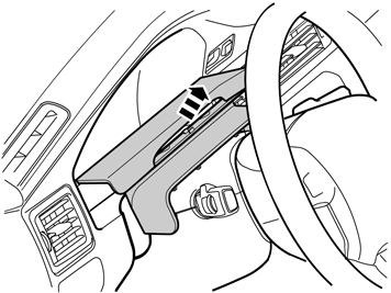
| | Carefully pull it off and remove the panel with the rubber seal. |
|  | | IMG-328978 |
|
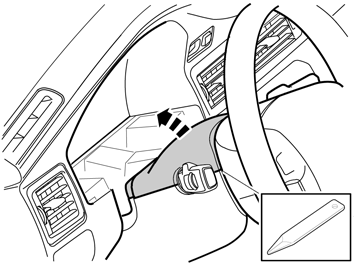
| | Carefully prize off the upper cover from the lower one at the rear. Remove the cover. It is fitted with clips at the sides. |
|  | | IMG-217441 |
|
| | |
|  | | IMG-328983 |
|
|  | | IMG-328989 |
|
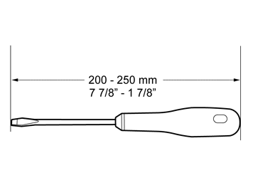
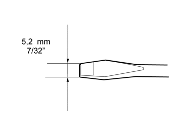
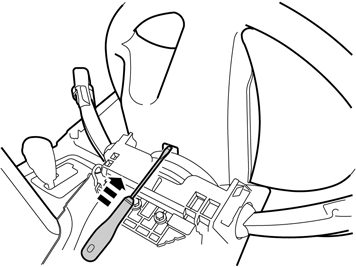
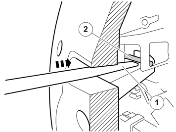
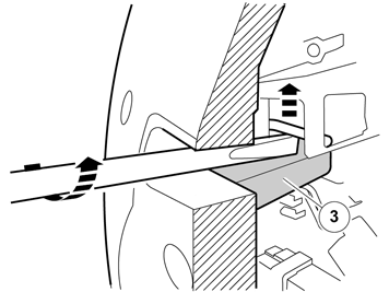
| | Illustrations A and B Use a screwdriver that is at least 5.2 mm wide and with a length of 200-250 mm. |
|  | | IMG-328990 |
|
|  | | IMG-329000 |
|
|  | | IMG-329001 |
|
|  | | IMG-329002 |
|
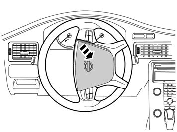
| | Illustration A Insert a screwdriver into the large hole on the rear of the steering wheel's rear face. Illustration B Insert the tip of the screwdriver (1) under the lock spring (2). Illustration C Turn the screwdriver so that the end presses the lock spring up until it can move past the locking catch (3) Illustration D Carefully pull off one side of the steering wheel module. It is firmly attached. Turn the steering wheel 180º. Repeat for the lock spring on the other side. Turn the steering wheel to neutral position. |
|  | | IMG-329003 |
|
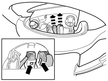
| | Carefully fold back the steering wheel module so that the connectors in the upper edge are accessible. Press in the catches on the connectors (small illustration) and detach them. Place the steering wheel module to one side
Caution!
Position the steering wheel module with the front upwards in a secure position while carrying out the work. |
|
|  | | IMG-329005 |
|
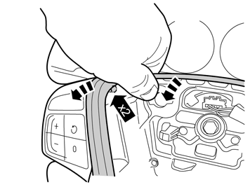
| | Grip the panel in the upper left-hand corner and carefully pull it loose until the pin releases. Use both hands. Repeat the operation on the other side. |
|  | | IMG-329006 |
|
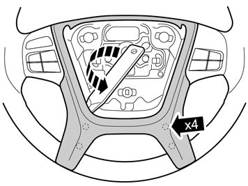
| | Use a weatherstrip tool, turn and carefully pull the panel loose at the bottom on both sides. Put it to one side. There is a new component in the kit. |
|  | | IMG-329007 |
|
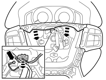
| | Unplug the green connector in the contact reel. Detach the ground cable from the bottom of the steering wheel. Detach the cables to the keypads from their positions in the steering wheel. |
|  | | IMG-329008 |
|
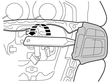
| | Remove the left and right-hand keypad/keypad dummy from the steering wheel by gently prizing them off with a plastic weatherstrip tool. Turn the weatherstrip tool to press out the keypad. They are firmly attached with three pins in the steering wheel, so force is required to remove them. |
|  | | IMG-329009 |
|
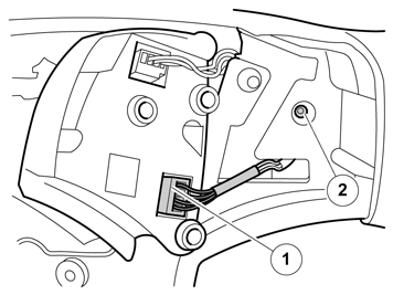
| | Applies to cars with an RTI keypad Unplug the connector (1) for the RTI keypad on the right keypad. Remove the screw (2). |
|  | | J6400900 |
|
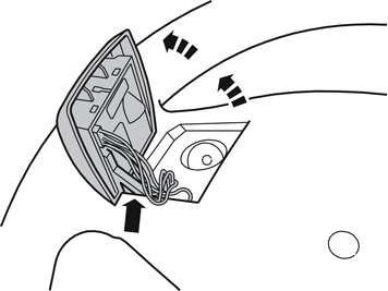
| | Pry up the keypad at the front edge and unhook it from the steering wheel at the rear edge Pull the cable out of the steering wheel. |
|  | | IMG-329010 |
|
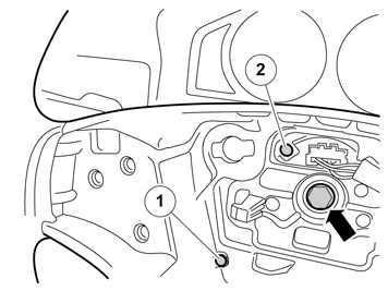
| | Applies to all models Loosen the screw in the steering wheel, but do not remove the screw. Take the screw (1) and screw it in the bracket (2) in the contact reel. Remove the screw and the steering wheel and put them to one side. Take the new steering wheel and screw from the kit |
|  | | J6400902 |
|
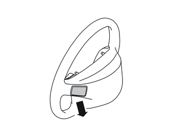
| | Applies to cars with an RTI keypad Remove the cover on the reverse of the right-hand spoke on the new steering wheel. |
|  | | IMG-329011 |
|
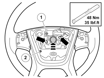
| | Applies to all models Take the new steering wheel and align the guide pins in the contact reel in the holes in the steering wheel. Take a new screw for the steering wheel and screw it in by hand. Remove the screw in the bracket (1) in the contact reel and reinsert it in position (2). Tighten and torque tighten the steering wheel screw. |
|  | | IMG-329012 |
|
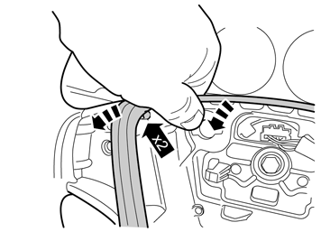
| | Grip the panel in the upper left-hand corner and carefully pull it loose until the pin releases. Use both your hands. Repeat the operation on the other side. |
|  | | IMG-329013 |
|
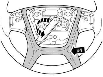
| | Use a weatherstrip tool, turn and carefully pull the panel loose at the bottom on both sides. |
|  | | IMG-329188 |
|
|  | | IMG-329014 |
|
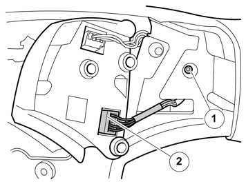
| | Applies to cars with an RTI keypad Illustrations A and B Insert the cables for the RTI keypad on the back of the steering wheel and pull them forward. Reinstall the keypad on the reverse of the steering wheel. Tighten using the screw (1). Plug in the connector (2) for the steering wheel's right-hand keypad. |
|  | | IMG-329016 |
|
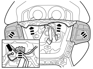
| | Applies to all models Refit the keypads. Fit the cables in their grooves. Plug in the green connector in the contact reel. Tighten the ground cable. |
|  | | IMG-329018 |
|
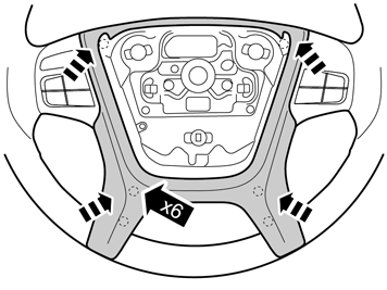
| | Take the panel and firmly press into the steering wheel. |
|  | | IMG-329019 |
|
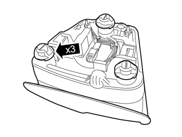
| | Take the steering wheel module and check that the three spring-loaded holders are firmly attached to it. If any holder has become trapped in the bottom of the steering wheel, remove it and fit it on the steering wheel module. |
|  | | IMG-329020 |
|
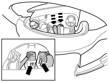
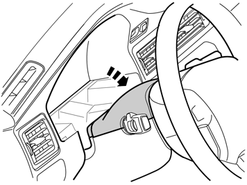
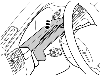
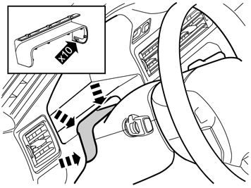
| | Plug in the two connectors for the steering wheel module. Position the steering wheel module in the centre of the steering wheel and press it firmly into bottom of the steering wheel. Check that it is fitted firmly and can be pressed in all around. |
|  | | IMG-329021 |
|
| | |
|  | | IMG-329022 |
|
| | |
|  | | IMG-329023 |
|
| | |
|  | | IMG-236182 |
|
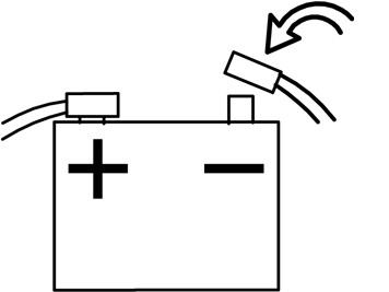
| | Installing the negative lead after working with SRS components
Warning!
Make sure that no one is in the vehicle during this procedure. |
Activate the SRS system in accordance with: "VIDA/ DIAGNOSTICS/ VEHICLE COMMUNICATION/ Advanced/ SRS/ Powering the SRS system" before turning the ignition key. Initiate window position in accordance with: "VIDA/ DIAGNOSTICS/ VEHICLE COMMUNICATION/ Advanced/ Initiating window position" |


