| | |
| | Read through all of the instructions before starting installation. Notifications and warning texts are for your safety and to minimise the risk of something breaking during installation. Ensure that all tools stated in the instructions are available before starting installation. Certain steps in the instructions are only presented in the form of images. Explanatory text is also given for more complicated steps. In the event of any problems with the instructions or the accessory, contact your local Volvo dealer.
|
| | |
| | When installing, the car must retain a temperature of 20 degrees C. After installation, the car must not be washed for 48 hours After installation, the car must not be driven for 2 hours There may be parts in the accessories kit that are not needed for this installation. |
| | |
|  | | IMG-363036 |
|
| | Note!
This colour chart displays (in colour print and electronic version) the importance of the different colours used in the images of the method steps. |
Used for focused component, the component with which you will do something. Used as extra colors when you need to show or differentiate additional parts. Used for attachments that are to be removed/installed. May be screws, clips, connectors, etc. Used when the component is not fully removed from the vehicle but only hung to the side. Used for standard tools and special tools. Used as background color for vehicle components.
|
| | |
|  | | IMG-384329 |
|
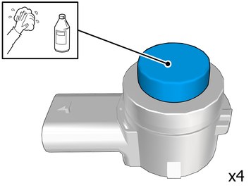
| | Clean the surface. Use: 1161721, Isopropanol
Allow to dry. |
|  | | IMG-384549 |
|
| | Clean the surface. Use: 1161721, Isopropanol
Allow to dry. |
|  | | IMG-384318 |
|
| | |
|  | | IMG-384550 |
|
| | |
|  | | IMG-384321 |
|
| | Clean the surface. Use: 1161721, Isopropanol
Allow to dry. |
|  | | IMG-384575 |
|
| | Clean the surface. Use: 1161721, Isopropanol
Allow to dry. |
|  | | IMG-384322 |
|
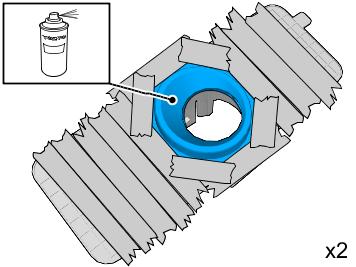
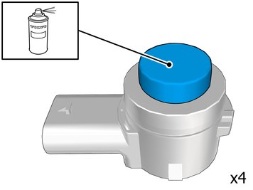
| | Use: 31335448, Bonding primer, plastic
Also see the instructions on the container. |
|  | | IMG-384576 |
|
| | Use: 31335448, Bonding primer, plastic
Also see the instructions on the container. |
|  | | IMG-384372 |
|
| | |
|  | | IMG-384853 |
|
| | |
|  | | IMG-404275 |
|
| | Clean the surface. Use: 1161721, Isopropanol
Allow to dry. |
|  | | IMG-404276 |
|
| | Matt the surface gently. Use: , Sand paper P1000
|
|  | | IMG-404277 |
|
| | Clean the surface. Use: 1161721, Isopropanol
Allow to dry. |
|  | | IMG-404278 |
|
| | Caution!
Protect connector surfaces against paint spray. |
Note!
Paint the sensors the same colour code as the vehicle. |
Use: , Volvo Original Touch-up paint
Use: 31335447, Varnish 2-component
Also see the instructions on the container. |
| | | IMG-384322 |
|
| | Note!
Use correct color following the vehicle's paint code. |
Use: , Volvo Original Touch-up paint
Use: 31335447, Varnish 2-component
Also see the instructions on the container. |
| | | IMG-384576 |
|
| | Note!
Use correct color following the vehicle's paint code. |
Use: , Volvo Original Touch-up paint
Use: 31335447, Varnish 2-component
Also see the instructions on the container. |
|  | | IMG-384373 |
|
| | Caution!
First the paint must dry after painting. |
|
|  | | IMG-384851 |
|
| | Caution!
First the paint must dry after painting. |
|
|  | | IMG-384320 |
|
| | |
|  | | IMG-384574 |
|
| | |
| | |
| | Note!
The removal steps may contain installation details. |
|
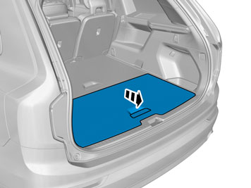
|  | | IMG-390109 |
|
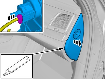
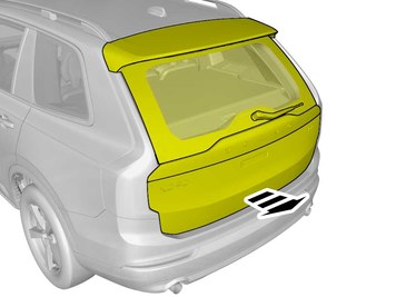
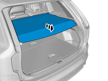
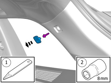
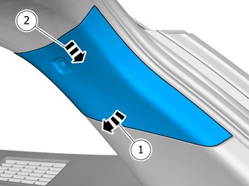
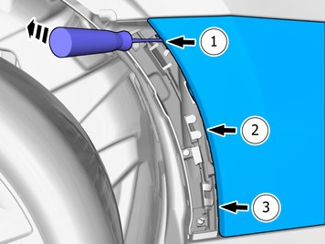
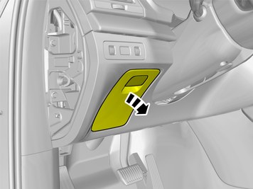
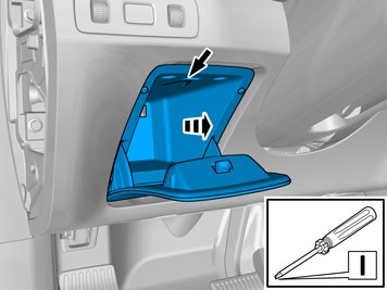
| | Remove the panel. Disconnect the connector, if applicable. |
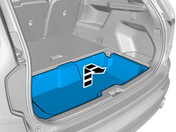
|  | | IMG-390116 |
|
| | |
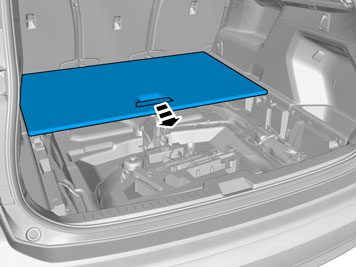
|  | | IMG-390091 |
|
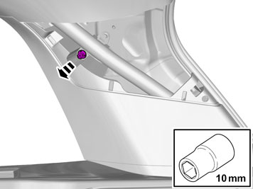
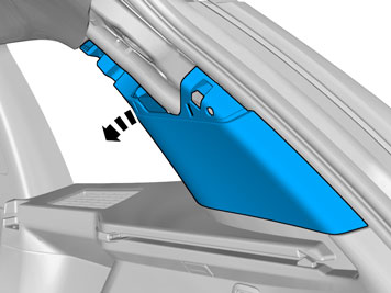
| | Disconnect the connector, if applicable. |
|  | | IMG-390106 |
|
| | |
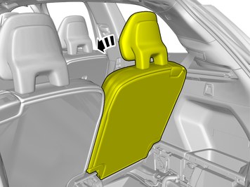
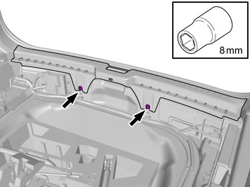
|  | | IMG-383237 |
|
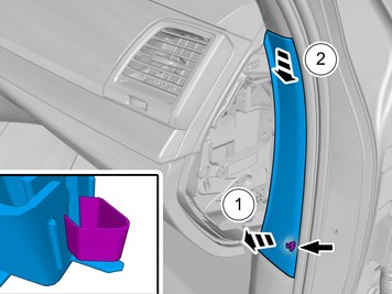
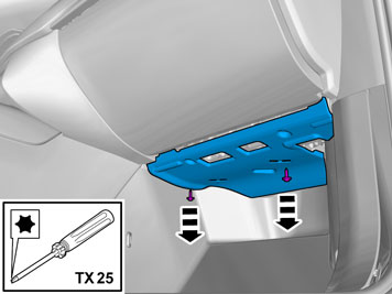
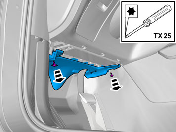
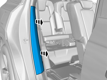
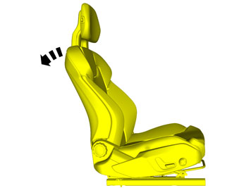
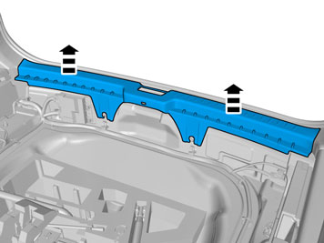
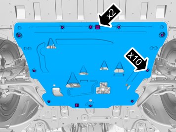
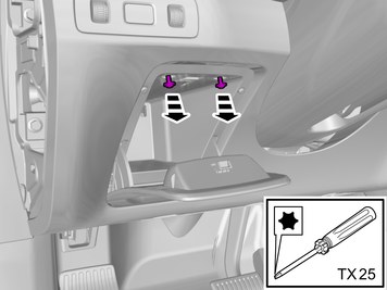
| | Remove the screws. Remove the panel. |
|  | | IMG-383729 |
|
| | |
|  | | IMG-383314 |
|
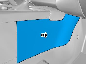
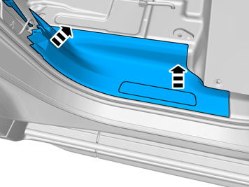
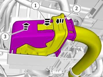
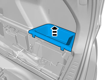
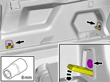
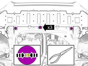
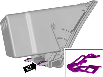
| | Remove the screws. Detach the panel. |
|  | | IMG-383315 |
|
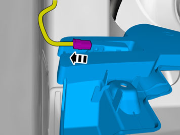
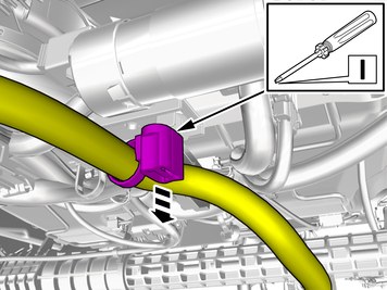
| | Disconnect the connector. Remove the panel. |
|  | | IMG-397295 |
|
| | |
|  | | IMG-383235 |
|
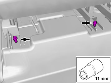
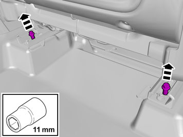
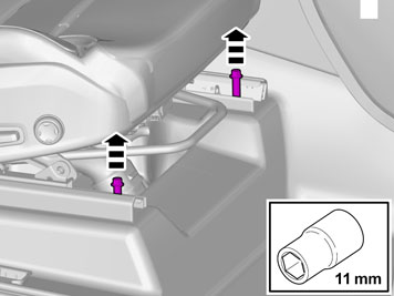
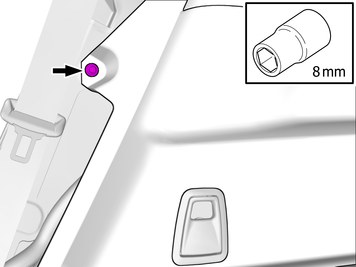
| | Remove the screws.
Tightening torque: Rear seat, to body
, 40 Nm
|
|  | | IMG-383236 |
|
| | Remove the screws.
Tightening torque: Rear seat, to body
, 40 Nm
|
|  | | IMG-404382 |
|
| | Disconnect the connector. |
|  | | IMG-404383 |
|
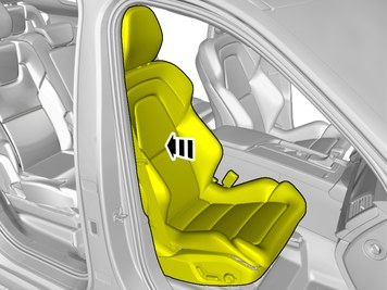
| | Caution!
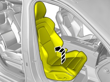
Be extra careful when removing or installing this component. |
|
|  | | IMG-404384 |
|
| | |
|  | | IMG-383234 |
|
| | |
|  | | IMG-383130 |
|
| | Remove the screws.
Tightening torque: Rear seat, to body
, 40 Nm
|
|  | | IMG-397249 |
|
| | |
|  | | IMG-383129 |
|
| | Remove the screws.
Tightening torque: Rear seat, to body
, 40 Nm
|
|  | | IMG-383134 |
|
| | |
|  | | IMG-396605 |
|
| | Disconnect the connector. |
|  | | IMG-396606 |
|
| | Unhook the cable harness clips. |
|  | | IMG-397624 |
|
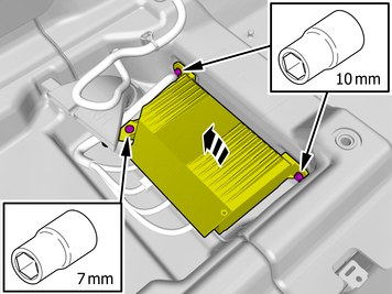
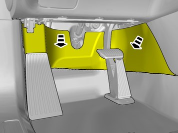
| | Remove the screws. Fold marked part aside. |
|  | | IMG-397637 |
|
| | |
|  | | IMG-404390 |
|
| | |
|  | | IMG-394779 |
|
| | |
|  | | IMG-383039 |
|
| | |
|  | | IMG-383043 |
|
| | |
|  | | IMG-383044 |
|
| | |
|  | | IMG-383045 |
|
| | |
|  | | IMG-383046 |
|
| | |
|  | | IMG-383040 |
|
| | |
|  | | IMG-394727 |
|
| | |
| | Vehicles with seven seats |
|  | | IMG-401374 |
|
| | |
| | Applies to all other vehicles |
|  | | IMG-383042 |
|
| | |
| | |
|  | | IMG-383047 |
|
| | Note!
Do not loosen the bolts more than 2 turns. |
|
|  | | IMG-383048 |
|
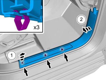
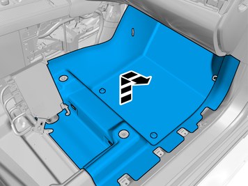
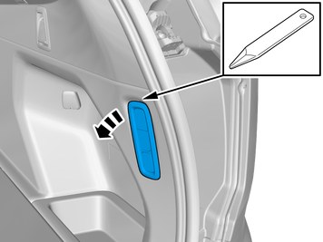
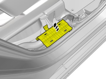
| | Remove the panel. Check that the fasteners are undamaged before installation. If not, they must be replaced with new ones. |
|  | | IMG-383066 |
|
| | |
|  | | IMG-393945 |
|
| | Remove the screws.
Tightening torque: Cargo anchor, to body
, 13 Nm
|
|  | | IMG-396625 |
|
| | |
| | Vehicles with air suspension |
|  | | IMG-398660 |
|
| | |
|  | | IMG-398661 |
|
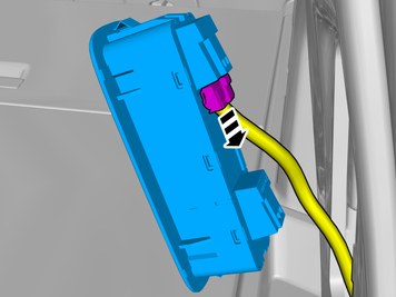
| | Disconnect the connector. |
| | |
|  | | IMG-383049 |
|
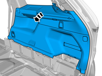
| | Remove the panel. Disconnect any connector(s). |
|  | | IMG-398662 |
|
| | Remove the marked part. Repeat on the other side. Make sure that the components are not mixed up at the installation. |
|  | | IMG-398676 |
|
| | |
|  | | IMG-398664 |
|
| | |
|  | | IMG-398850 |
|
| | Fold the wing liner aside. |
|  | | IMG-402988 |
|
| | Release the catches. Remove the part carefully |
|  | | IMG-402987 |
|
| | Remove the part carefully |
|  | | IMG-402986 |
|
| | Release the catches. Remove the part carefully |
|  | | IMG-401258 |
|
| | Release the catches. Remove the part carefully |
|  | | IMG-398711 |
|
| | |
|  | | IMG-400000 |
|
| | Repeat the steps when removing on opposite side. |
|  | | IMG-384129 |
|
| | Disconnect the connector. |
|  | | IMG-398685 |
|
| | Caution!
Place the Bumper Cover on a suitable surface. |
Request the aid of a colleague for this procedure. |
| | |
|  | | IMG-384153 |
|
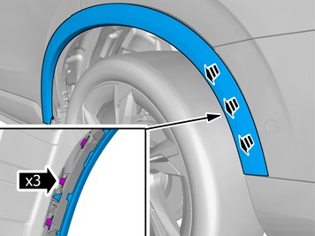
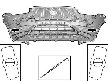
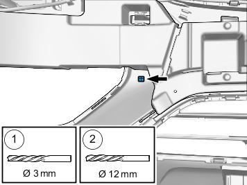
| | Locate the markings for the positions. Measure and mark out the centre. Use: Scribe
|
|  | | IMG-384154 |
|
| | |
|  | | IMG-384173 |
|
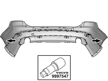
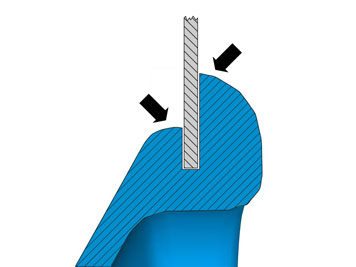
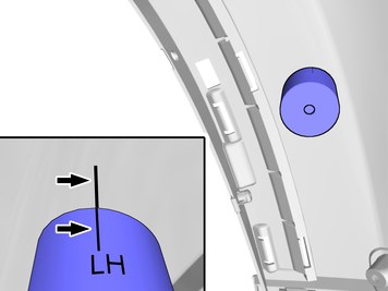
| | Caution!
Sharp end of tool must be on outside of cover. |
Use special tool: T9997547, Hole punch
|
|  | | IMG-384293 |
|
| | Clean the surfaces. Use: 1161721, Isopropanol
Allow to dry. |
|  | | IMG-384289 |
|
| | Apply a thin and even layer. Use: 1161765, Primer
Allow to dry for at least 2 minutes, but no more than 60minutes. |
|  | | IMG-384483 |
|
| | Clean the surfaces. Use: 1161721, Isopropanol
Allow to dry. |
|  | | IMG-384484 |
|
| | Apply a thin and even layer. Use: 1161765, Primer
Allow to dry for at least 2 minutes, but no more than 60minutes. |
| | Note!
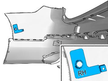
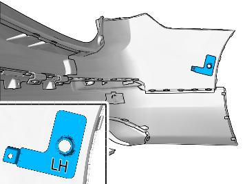
Prepare and install one holder at a time. |
|
|  | | IMG-384485 |
|
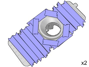
| | Note!
Ensure that the tape is fixed to the surface. |
|
|  | | IMG-384507 |
|
| | Clean the surface. Use: 1161721, Isopropanol
Allow to dry. |
|  | | IMG-384488 |
|
| | Remove the protective film. |
|  | | IMG-384493 |
|
| | Warning!
Wear protective gloves. |
Warning!
Make sure to provide adequate ventilation. |
Use special tool: T9512950, Glue gun (kit)
Use: 9511027, Glue
Use: 1161730, Mixing pipe
|
|  | | IMG-384641 |
|
| | |
|  | | IMG-384652 |
|
| | |
|  | | IMG-409427 |
|
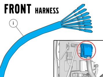
| | Disconnect the connectors. Attach the connector to the wiring harness. |
|  | | IMG-409435 |
|
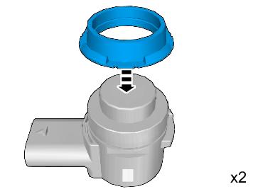
| | Install component that comes with the accessory kit. Put the wiring in the Bumper cover without installing the wiring. |
|  | | IMG-467106 |
|
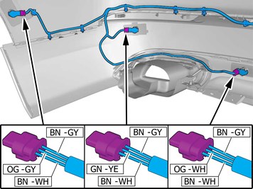
| | BN = Brown GY = Grey WH = White OG = Orange GN = Green YE = Yellow |
|  | | IMG-467107 |
|
| | BN = Brown GY = Grey WH = White OG = Orange YE = Yellow |
|  | | IMG-384661 |
|
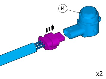
| | Connect the two painted sensors to the external connections. Repeat on the other side. |
|  | | IMG-409440 |
|
| | Connect the cable harness. |
|  | | IMG-409445 |
|
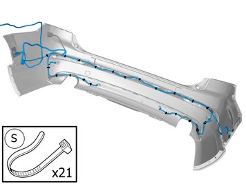
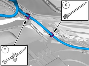
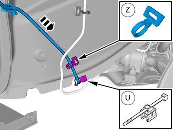
| | Route the cable harness to the existing cable harness. Install the wiring harness. Use a cable tie |
|  | | IMG-386729 |
|
| | The part is not to be reused. |
|  | | IMG-409450 |
|
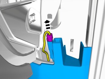
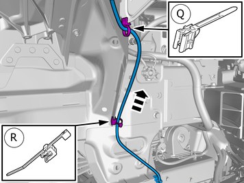
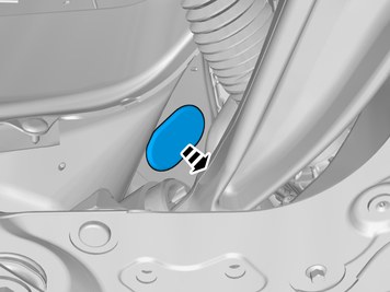
| | Route the wiring harness into the passenger compartment. |
|  | | IMG-409455 |
|
| | Request the aid of a colleague for this procedure. Place the Bumper Cover in position for installation. |
|  | | IMG-403340 |
|
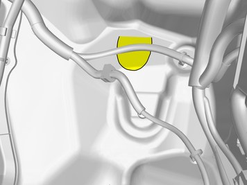
| | |
|  | | IMG-358177 |
|
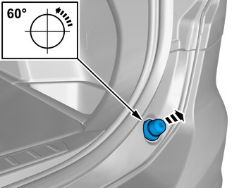
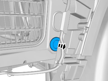
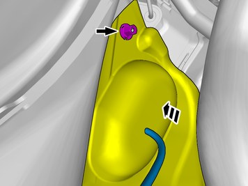
| | Caution!
Make sure that the rubber grommet seals properly to the body. |
|
|  | | IMG-409500 |
|
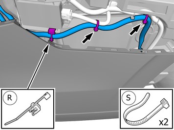
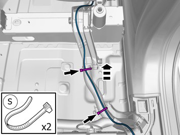
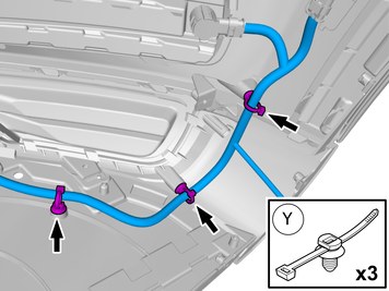
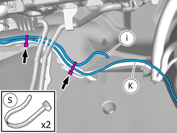
| | Install the wiring harness. Use a cable tie |
| | |
|  | | IMG-384699 |
|
| | |
|  | | IMG-383543 |
|
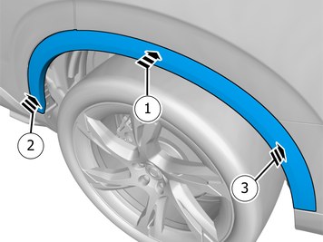
| | Reinstall the bumper. Repeat on the other side. |
|  | | IMG-402997 |
|
| | Note!
Make sure to follow the sequence indicated. |
Reinstall the removed part. Ensure that all clips engage. Repeat on the other side. |
| | |
|  | | IMG-386748 |
|
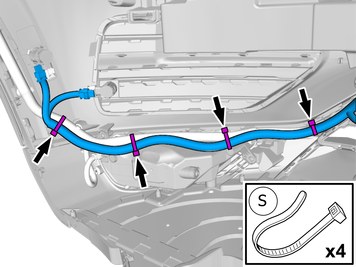
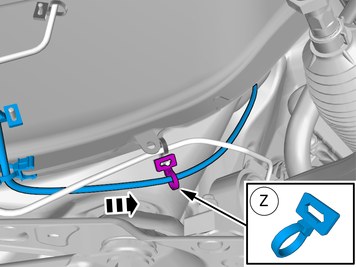
| | Route the cable harness to the existing cable harness. Install the wiring harness. Use a cable tie |
|  | | IMG-386753 |
|
| | Route the cable harness to the existing cable harness. Install the wiring harness. Use a cable tie |
|  | | IMG-397598 |
|
| | |
|  | | IMG-402306 |
|
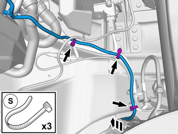
| | Route the cable harness to the existing cable harness. Install the wiring harness. Use a cable tie |
|  | | IMG-383238 |
|
| | |
|  | | IMG-404485 |
|
| | |
|  | | IMG-383244 |
|
| | Route the cable harness to the existing cable harness. Install the wiring harness. Use a cable tie |
|  | | IMG-404500 |
|
| | Route the cable harness to the existing cable harness. Install the wiring harness. Use a cable tie |
|  | | IMG-397252 |
|
| | |
|  | | IMG-383240 |
|
| | Route the cable harness to the existing cable harness. |
|  | | IMG-402310 |
|
| | Route the cable harness to the existing cable harness. Install the wiring harness. Use a cable tie |
| | |
|  | | IMG-382528 |
|
| | |
|  | | IMG-382209 |
|
| |
Tightening torque: Aluminum wheel rim to wheel hub
Stage 1:
4 Nm
Stage 2:
50 Nm
Stage 3:
140 Nm
Repeat on the other side. |
|  | | IMG-382210 |
|
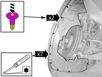
| | Remove the screws. Repeat on the other side. |
|  | | IMG-382280 |
|
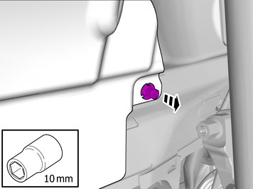
| | Remove the nut. Repeat on the other side. |
|  | | IMG-382211 |
|
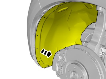
| | Fold the wing liner aside. Repeat on the other side. |
|  | | IMG-396574 |
|
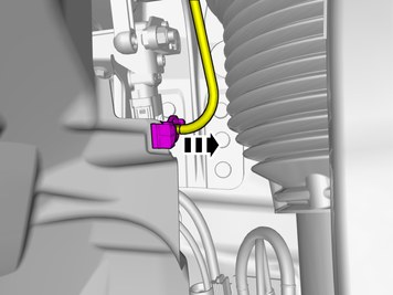
| | Disconnect the connector. |
| | |
|  | | IMG-382216 |
|
| | Remove the screws. Repeat on the other side. |
| | |
|  | | IMG-412857 |
|
| | Remove the screws. Repeat on the other side. |
| | |
|  | | IMG-398082 |
|
| | Repeat on the other side. |
|  | | IMG-398324 |
|
| | Repeat on the other side. |
| | Vehicles with headlamp washers |
|  | | IMG-396579 |
|
| | Warning!
Be prepared to collect escaping fluid. |
|
| | |
|  | | IMG-402167 |
|
| | |
|  | | IMG-402166 |
|
| | Remove the clip. Remove the nut. |
| | Vehicles with air suspension |
|  | | IMG-406668 |
|
| | |
| | |
|  | | IMG-402163 |
|
| | |
| | |
|  | | IMG-382204 |
|
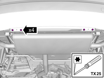
| | Remove the clips. Remove the screws. |
|  | | IMG-387143 |
|
| | |
|  | | IMG-398535 |
|
| | |
|  | | IMG-382200 |
|
| | |
|  | | IMG-382201 |
|
| | |
|  | | IMG-398087 |
|
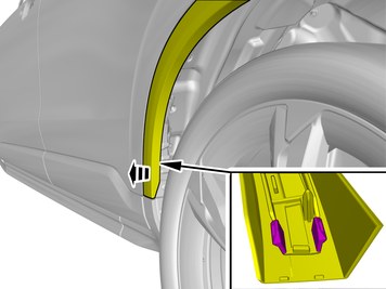
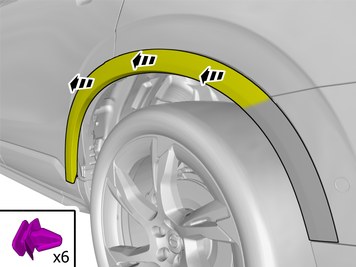
| | Remove the clips. Remove the marked part. Repeat on the other side. |
|  | | IMG-386979 |
|
| | Repeat on the other side. |
|  | | IMG-387146 |
|
| | Note!
This step is easier with two people. |
|
| | |
|  | | IMG-386146 |
|
| | Locate the markings for the positions. Mark the centre. Use: Scribe
|
|  | | IMG-402106 |
|
| | Measure and mark as illustrated. Use: Scribe
|
|  | | IMG-386150 |
|
| | |
|  | | IMG-401855 |
|
| | Note!
Check that the markings are opposite each other and that they are pointing upwards when the tool is used. |
Use special tool: T9997548, Hole punch
|
|  | | IMG-386151 |
|
| | Caution!
Sharp end of tool must be on outside of cover. |
|
|  | | IMG-401879 |
|
| | Note!
Check that the markings are opposite each other and that they are pointing upwards when the tool is used. |
|
|  | | IMG-386154 |
|
| | Clean the surfaces. Use: 1161721, Isopropanol
Allow to dry. |
|  | | IMG-386155 |
|
| | Apply a thin and even layer. Use: 1161765, Primer
Allow to dry for at least 2 minutes, but no more than 60minutes. |
|  | | IMG-384538 |
|
| | Clean the surfaces. Use: 1161721, Isopropanol
Allow to dry. |
|  | | IMG-384536 |
|
| | Apply a thin and even layer. Use: 1161765, Primer
Allow to dry for at least 2 minutes, but no more than 60minutes. |
|  | | IMG-386162 |
|
| | Note!
Prepare and install one holder at a time. |
Install component that comes with the accessory kit. |
|  | | IMG-386164 |
|
| | Clean the surface. Use: 1161721, Isopropanol
Allow to dry. |
|  | | IMG-384530 |
|
| | Remove the protective film. |
|  | | IMG-386165 |
|
| | Warning!
Wear protective gloves. |
Warning!
Make sure to provide adequate ventilation. |
Use special tool: T9512950, Glue gun (kit)
Use: 9511027, Glue
Use: 1161730, Mixing pipe
|
|  | | IMG-386174 |
|
| | |
|  | | IMG-386175 |
|
| | |
|  | | IMG-386127 |
|
| | The part is not to be reused. Repeat on the other side. |
|  | | IMG-386401 |
|
| | Locate relevant marking. Mark the centre. Repeat on the other side. |
|  | | IMG-386402 |
|
| | Repeat on the other side. |
|  | | IMG-386124 |
|
| | |
|  | | IMG-386125 |
|
| | Repeat on the other side. |
|  | | IMG-386384 |
|
| | Repeat on the other side. |
|  | | IMG-386130 |
|
| | Repeat on the other side. |
|  | | IMG-386466 |
|
| | Repeat on the other side. |
|  | | IMG-395202 |
|
| | Put the wiring in the Bumper cover without installing the wiring. RHD: The cable harness is positioned mirrored. |
|  | | IMG-420033 |
|
| | Connect the two painted sensors to the external connections. |
|  | | IMG-386852 |
|
| | Repeat on the other side. |
|  | | IMG-386851 |
|
| | Repeat on the other side. |
|  | | IMG-386850 |
|
| | Repeat on the other side. |
| | Vehicles without daytime running lamps (DRL) |
|  | | IMG-386847 |
|
| | Position/route the cable harness as illustrated. Install the wiring harness. Use a cable tie |
|  | | IMG-398123 |
|
| | Position/route the cable harness as illustrated. Install the wiring harness. Use a cable tie |
|  | | IMG-386844 |
|
| | Position/route the cable harness as illustrated. Install the wiring harness. Use a cable tie |
|  | | IMG-401906 |
|
| | Position/route the cable harness as illustrated. Install the wiring harness. Use a cable tie |
| | Vehicles with daytime running lamps (DRL) |
|  | | IMG-402126 |
|
| | Route the cable harness to the existing cable harness. Install the wiring harness. Use a cable tie |
|  | | IMG-402127 |
|
| | Route the cable harness to the existing cable harness. Install the wiring harness. Use a cable tie |
|  | | IMG-402129 |
|
| | Route the cable harness to the existing cable harness. Install the wiring harness. Use a cable tie |
|  | | IMG-402130 |
|
| | Route the cable harness to the existing cable harness. Install the wiring harness. Use a cable tie |
| | |
|  | | IMG-402135 |
|
| | Position/route the cable harness as illustrated. Install the wiring harness. Use a cable tie |
|  | | IMG-386842 |
|
| | |
|  | | IMG-402170 |
|
| | Position/route the cable harness as illustrated. Install the wiring harness. Use a cable tie |
|  | | IMG-402171 |
|
| | Position/route the cable harness as illustrated. Install the wiring harness. Use a cable tie |
|  | | IMG-402172 |
|
| | Position/route the cable harness as illustrated. Install the wiring harness. Use a cable tie |
| | Vehicles with fuel-driven heater |
|  | | IMG-402180 |
|
| | Position/route the cable harness as illustrated. Install the wiring harness. Use a cable tie |
|  | | IMG-402195 |
|
| | Position/route the cable harness as illustrated. Install the wiring harness. Use a cable tie |
| | Applies to all other vehicles |
|  | | IMG-402210 |
|
| | Position/route the cable harness as illustrated. Install the wiring harness. Use a cable tie |
|  | | IMG-405410 |
|
| | Position/route the cable harness as illustrated. Install the wiring harness. Use a cable tie |
|  | | IMG-405411 |
|
| | Position/route the cable harness as illustrated. Install the wiring harness. Use a cable tie |
|  | | IMG-386950 |
|
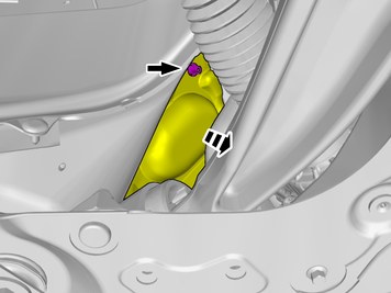
| | Remove the nut. Fold the insulation aside. |
|  | | IMG-402286 |
|
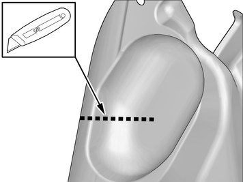
| | Make a cut in the insulation. |
|  | | IMG-386951 |
|
| | The part is not to be reused. |
|  | | IMG-386974 |
|
| | |
|  | | IMG-386994 |
|
| | Fold the insulation aside. |
|  | | IMG-402237 |
|
| | |
|  | | IMG-402238 |
|
| | Pull the wiring through. Use: 1161150, Lubricant
Use special tool: T9814204, Expander pliers
|
|  | | IMG-402275 |
|
| | Route the wiring harness into the passenger compartment. |
|  | | IMG-402277 |
|
| | Caution!
Make sure that the rubber grommet seals properly to the body. |
Insert the cable in to the passenger compartment, adjust the cable length out into the engine compartment and secure the rubber grommet. |
|  | | IMG-402285 |
|
| | |
|  | | IMG-386995 |
|
| | Position/route the cable as illustrated. |
|  | | IMG-402370 |
|
| | Install the cables. Use a cable tie |
|  | | IMG-386826 |
|
| | |
|  | | IMG-402386 |
|
| | Install the cables. Use a cable tie Position/route the cables as illustrated. |
| | |
|  | | IMG-387085 |
|
| | |
|  | | IMG-387086 |
|
| | |
|  | | IMG-403400 |
|
| | Note!
The graphic shows the back of the component before removal. |
|
|  | | IMG-387107 |
|
| | |
|  | | IMG-387123 |
|
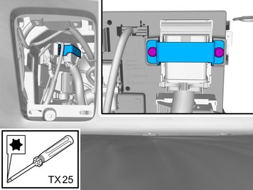
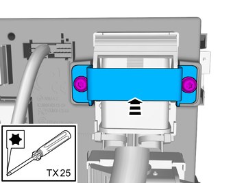
| | Remove the screws. Remove the marked part. |
|  | | IMG-387398 |
|
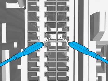
| | Depress the locking device. Release the connector's catch. Disconnect the connector.
|
|  | | IMG-387423 |
|
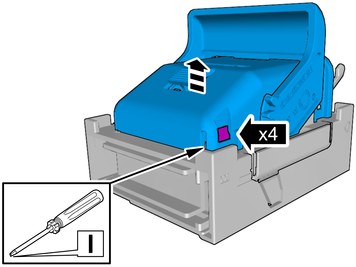
| | Release the catches. Remove the marked part. |
|  | | IMG-400415 |
|
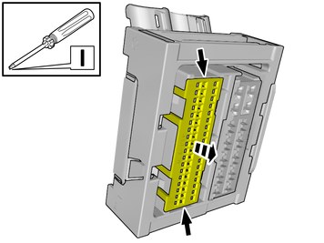
| | Release the connector's secondary lock. Lift approximately 2 mm. |
| | |
|  | | IMG-410552 |
|
| | |
|  | | IMG-387476 |
|
| | Connect the prerouted wiring harness. Connect the cable harness terminals in the connector as follows. |
|  | | IMG-402395 |
|
| | |
|  | | IMG-400383 |
|
| | Depress the secondary lock. |
|  | | IMG-387424 |
|
| | Reinstall the removed part. |
| | |
|  | | IMG-387415 |
|
| | Depress the locking device. Release the connector's catch. Disconnect the connector.
|
| | | IMG-387423 |
|
| | Release the catches. Remove the marked part. |
| | | IMG-400415 |
|
| | Release the connector's secondary lock. Lift approximately 2 mm. |
|  | | IMG-409615 |
|
| | Release the catches. Remove the marked part. |
|  | | IMG-409805 |
|
| |
Use special tool: T9512632, Terminal removal tool (Color code: RED)
|
|  | | IMG-409625 |
|
| | Disconnect terminals from the connector, following the graphic. |
| | |
|  | | IMG-410553 |
|
| | |
|  | | IMG-409560 |
|
| | Connect the prerouted wiring harness. Connect the cable harness terminals in the connector as follows. |
|  | | IMG-409561 |
|
| | |
|  | | IMG-409626 |
|
| | Depress the secondary lock. |
| | | IMG-387424 |
|
| | Reinstall the removed part. |
|  | | IMG-387144 |
|
| | |
|  | | IMG-387145 |
|
| | Reinstall the removed part. Reinstall the screws. |
|  | | IMG-403372 |
|
| | Install the cables. Use a cable tie |
|  | | IMG-400005 |
|
| | Caution!
A change to another tire size will cause changes in tire circumference. This will affect the Parking assistance pilot function. |
Check that the tire dimension stated in the vehicle configuration, corresponds to the actual tire dimension of the vehicle. If this does not correspond, download correct software. |
|  | | IMG-242268 |
|
| | Download software (application) for the accessory's function according to the service information in VIDA. |